Recent Posts

Friday, 3 November 2017

IPv6 Traffic Filtering ACL Configurations

Introduction

This document provides a sample configuration for IPv6 access lists. In the example described in this document, routers R1 and R2 are configured with IPv6 addressing scheme and connected through serial link. The routing protocol enabled on the two routers is IPv6 OSPF, and the loopback addresses configured on both the routers (R1 and R2) are advertised to each other in area 0 with this command: ipv6 ospf process-id area area-id . In this example, it is required to deny telnet traffic that originates from the loopback 0 interface of router R2 and reaches loopback interface 4 of router R1.
This configuration example uses the ipv6 access-list access-list-name command in order to construct an IPv6 access list (named DENY_TELNET_Lo4) on router R1. A deny statement deny tcp host 400A:0:400C::1 host 1001:ABC:2011:7::1 eq telnet is followed by a permit statement permit ipv6 any any .
In order to assign an IPv6 ACL to an interface, use this command in interface configuration mode: ipv6 traffic-filter access-list-name {in | out}

Requirements

Ensure that you meet these requirements before you attempt this configuration:
  • Knowledge of IPv6 Addressing Scheme
  • Knowledge of Implementing OSPF for IPv6

Components Used

The information in this document is based on the Cisco 7200 series router on Cisco IOS Software Release 15.1 (for routers R1 and R2 configurations).

Configure

In this section, you are presented with the information to configure the features described in this document.

Network Diagram

This document uses this network setup:
ipv6-acl-01.gif


Configurations

This document uses these configurations:
ROUTER 1
R1#show running-config
version 15.0
!
hostname R1
ip source-route
ip cef
!
no ip domain lookup
ipv6 unicast-routing

!--- Enables the forwarding of IPv6 packets.

ipv6 cef

interface Loopback1
 no ip address
 ipv6 address 100A:0:100C::1/64
 ipv6 enable
 ipv6 ospf 10 area 0

!--- Enables OSPFv3 on the interface and associates


!--- the interface looback1 to area 0.

 !
!
interface Loopback2
 no ip address
 ipv6 address 200A:0:200C::1/64
 ipv6 ospf 10 area 0
 !
!
interface Loopback3
 no ip address
 ipv6 address 300A:0:300C::1/64
 ipv6 enable
 ipv6 ospf 10 area 0
 !
!
interface Loopback4
 no ip address
 ipv6 address 400A:0:400C::1/64
 ipv6 enable
 ipv6 ospf 10 area 0
 !
interface Serial1/0
 no ip address
 ipv6 address AB01:2011:7:100::/64 eui-64
 ipv6 enable
 ipv6 ospf network point-to-point

!--- Sets the OSPFv3 network type as point-to-point.

 ipv6 ospf 10 area 0
 ipv6 traffic-filter DENY_TELNET_Lo4 in

!--- Filters the traffic based on access list.

 serial restart-delay 0
 clock rate 64000
 !
ipv6 router ospf 10
 router-id 1.1.1.1
 log-adjacency-changes
!
ipv6 access-list DENY_TELNET_Lo4
 sequence 20 deny tcp host 400A:0:400C::1 host 1001:ABC:2011:7::1 eq telnet

!--- Denies telnet access to Lo4 from Lo1 of router R2.

 permit ipv6 any any
!
end
ROUTER 2
R2#show running-config

version 15.0
hostname R2
ip source-route
ip cef
!
no ip domain lookup
ipv6 unicast-routing
ipv6 cef
!
interface Loopback 0
 no ip address
 ipv6 address 1001:ABC:2011:7::1/64
 ipv6 enable
 ipv6 ospf 10 area 0
 !
!
interface Serial1/0
 no ip address
 ipv6 address AB01:2011:7:100::/64 eui-64
 ipv6 enable
 ipv6 ospf network point-to-point
 ipv6 ospf 10 area 0
 serial restart-delay 0
 !
ipv6 router ospf 10
 router-id 2.2.2.2
 log-adjacency-changes
!
end

Verify

In order to verify the configuration, use the ping command.
On Router R2
This sample output shows that router R2 can reach the loopback interface of router R1:
R2#ping ipv6 400A:0:400C::1 source lo 0
Type escape sequence to abort.
Sending 5, 100-byte ICMP Echos to 400A:0:400C::1, timeout is 2 seconds:
Packet sent with a source address of 1001:ABC:2011:7::1
!!!!!
Success rate is 100 percent (5/5), round-trip min/avg/max = 20/32/44 ms
Try telnet loopback 4 interface of router R1 from the loopback 0 interface of router R2.
R2#telnet 400A:0:400C::1 /source-interface lo 0
Trying 400A:0:400C::1, 23 ...
% Connection refused by remote host
On Router R1
R1#show ipv6 access-list DENY_TELNET_Lo4 
IPv6 access list DENY_TELNET_Lo4
deny tcp host 400A:0:400C::1 host 1001:ABC:2011:7::1 eq telnet sequence 20
permit ipv6 any any (82 matches) sequence 30


Thursday, 2 November 2017

REVIEW on MultiCast

Overview
IP multicast is a technique for one-to-many and many-to-many real-time communication over an IP infrastructure in a network. It scales to a larger receiver population by requiring neither prior knowledge of a receiver's identity nor prior knowledge of the number of receivers. Multicast uses network infrastructure efficiently by requiring the source to send a packet only once, even if it needs to be delivered to a large number of receivers. The nodes in the network (typically network switches and routers) take care of replicating the packet to reach multiple receivers such that messages are sent over each link of the network only once.

What is Multicast ?
In computer networkingmulticast is group communication where data transmission is addressed to a group of destination computers simultaneously.Multicast can be one-to-many or many-to-many distribution. Multicast should not be confused with physical layer point-to-multi point communication.

 Image result for multicast network

Which version of IP supports Multicast ?
IP multicast is the IP-specific version of the general concept of multicast networking. It uses specially reserved multicast address blocks in IPv4 and IPv6.


Why we need Multicast ? ....and its Practical application?
Protocols associated with IP multicast include Internet Group Management Protocol, Protocol Independent Multicast and Multicast VLAN Registration. IGMP snooping is used to manage IP multicast traffic on layer-2 networks.

What are other or different type of CAST ?  in the IPv6 ... 

1. Unicast - to transmit a single message to a single receiver. 


2. Multicast - to transmit a single message to a select group of recipients. A simple example of multi casting is sending an e-mail message to a mailing list. Teleconferencing and videoconferencing also use multicasting, and often use proprietary protocols in addition to the existing multicast standards (IP Multicast, Mbone, etc).  


3. Narrowcast - to transmit a single message to a select group of recipients who have subscribed. Narrowcast is similar to Multicast and the two terms are often used interchangeably.  However, narrowcast refers to the business model whereas multicast refers to the actual technology used to transmit the data. Cable television is an example of narrowcasting since the cable TV signals are sent only to homes that have subscribed to the cable service.  Perhaps the best example of narrowcasting are e-mail lists where messages are sent only to individuals who subscribe to the list.


4. Broadcast - to transmit a single message to everyone connected to a network.  Note that multicasting refers to sending a message to a select group whereas broadcasting refers to sending a message to everyone connected to a network.


5. Anycast (IPv6) - to transmit a single message to the nearest of a group of receivers. Anycast is used in IPv6 as a method of updating routing tables, as in the 6 to 4 Anycast protocol. One host initiates an update of a router table for a group of hosts, sending the data to the nearest host. That host then sends the message on to its nearest router until all the routing tables in that group are updated.


Why there is no Subnetting in IPv6 ? What's the equivalent or Replacement?

1: IPv6 addresses are 128-bit hexadecimal numbers

The IPv4 addresses we are all used to seeing are made up of four numerical octets that combine to form a 32-bit address. IPv6 addresses look nothing like IPv4 addresses. IPv6 addresses are 128 bits in length and are made up of hexadecimal characters.
In IPv4, each octet consists of a decimal number ranging from 0 to 255. These numbers are typically separated by periods. In IPv6, addresses are expressed as a series of eight 4-character hexadecimal numbers, which represent 16 bits each (for a total of 128 bits). As we'll see in a minute, IPv6 addresses can sometimes be abbreviated in a way that allows them to be expressed with fewer characters.

2: Link local unicast addresses are easy to identify

IPv6 reserves certain headers for different types of addresses. Probably the best known example of this is that link local unicast addresses always begin with FE80. Similarly, multicast addresses always begin with FF0x, where the x is a placeholder representing a number from 1 to 8.

3: Leading zeros are suppressed

Because of their long bit lengths, IPv6 addresses tend to contain a lot of zeros. When a section of an address starts with one or more zeros, those zeros are nothing more than placeholders. So any leading zeros can be suppressed. To get a better idea of what I mean, look at this address:
FE80:CD00:0000:0CDE:1257:0000:211E:729C
If this were a real address, any leading zero within a section could be suppressed. The result would look like this:
FE80:CD00:0:CDE:1257:0:211E:729C
As you can see, suppressing leading zeros goes a long way toward shortening the address.

4: Inline zeros can sometimes be suppressed

Real IPv6 addresses tend to contain long sections of nothing but zeros, which can also be suppressed. For example, consider the address shown below:
FE80:CD00:0000:0000:0000:0000:211E:729C
In this address, there are four sequential sections separated by zeros. Rather than simply suppressing the leading zeros, you can get rid of all of the sequential zeros and replace them with two colons. The two colons tell the operating system that everything in between them is a zero. The address shown above then becomes:
FE80:CD00::211E:729C
You must remember two things about inline zero suppression. First, you can suppress a section only if it contains nothing but zeros. For example, you will notice that the second part of the address shown above still contains some trailing zeros. Those zeros were retained because there are non-zero characters in the section. Second, you can use the double colon notation only once in any given address.

5: Loopback addresses don't even look like addresses

In IPv4, a designated address known as a loopback address points to the local machine. The loopback address for any IPv4-enabled device is 127.0.0.1.
Like IPv4, there is also a designated loopback address for IPv6:
0000:0000:0000:0000:0000:0000:0000:0001
Once all of the zeros have been suppressed, however, the IPv6 loopback address doesn't even look like a valid address. The loopback address is usually expressed as ::1.

6: You don't need a traditional subnet mask

In IPv4, every IP address comes with a corresponding subnet mask. IPv6 also uses subnets, but the subnet ID is built into the address.
In an IPv6 address, the first 48 bits are the network prefix. The next 16 bits are the subnet ID and are used for defining subnets. The last 64 bits are the interface identifier (which is also known as the Interface ID or the Device ID).
If necessary, the bits that are normally reserved for the Device ID can be used for additional subnet masking. However, this is normally not necessary, as using a 16-bit subnet and a 64-bit device ID provides for 65,535 subnets with quintillions of possible device IDs per subnet. Still, some organizations are already going beyond 16-bit subnet IDs.

7: DNS is still a valid technology

In IPv4, Host (A) records are used to map an IP address to a host name. DNS is still used in IPv6, but Host (A) records are not used by IPv6 addresses. Instead, IPv6 uses AAAA resource records, which are sometimes referred to as Quad A records. The domain ip6.arpa is used for reverse hostname resolution.

8: IPv6 can tunnel its way across IPv4 networks

One of the things that has caused IPv6 adoption to take so long is that IPv6 is not generally compatible with IPv4 networks. As a result, a number of transition technologies use tunneling to facilitate cross network compatibility. Two such technologies are Teredo and 6to4. Although these technologies work in different ways, the basic idea is that both encapsulate IPv6 packets inside IPv4 packets. That way, IPv6 traffic can flow across an IPv4 network. Keep in mind, however, that tunnel endpoints are required on both ends to encapsulate and extract the IPv6 packets.

9: You might already be using IPv6

Beginning with Windows Vista, Microsoft began installing and enabling IPv6 by default. Because the Windows implementation of IPv6 is self-configuring, your computers could be broadcasting IPv6 traffic without your even knowing it. Of course, this doesn't necessarily mean that you can abandon IPv4. Not all switches and routers support IPv6, just as some applications contain hard-coded references to IPv4 addresses.

10: Windows doesn't fully support IPv6

It's kind of ironic, but as hard as Microsoft has been pushing IPv6 adoption, Windows does not fully support IPv6 in all the ways you might expect. For example, in Windows, it is possible to include an IP address within a Universal Naming Convention (\\127.0.0.1\C$, for example). However, you can't do this with IPv6 addresses because when Windows sees a colon, it assumes you're referencing a drive letter.
To work around this issue, Microsoft has established a special domain for IPv6 address translation. If you want to include an IPv6 address within a Universal Naming Convention, you must replace the colons with dashes and append .ipv6 to the end of the address — for example, FE80-AB00—200D-617B ipv6.

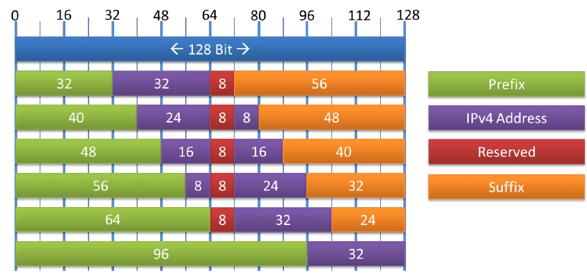
Related image

Analyze IPv4 vs IPv6 - HEADERS ?
• IPv6 header is much simpler than IPv4 header.
• The size of IPv6 header is much bigger than that of IPv4 header, because of IPv6 address size. IPv4 addresses are 32bit binary numbers and IPv6 addresses are 128 bit binary numbers.
• In IPv4 header, the source and destination IPv4 addresses are 32 bit binary numbers. In IPv6 header, source and destination IPv6 addresses are 128 bit binary numbers.
• IPv4 header includes space for IPv4 options. In IPv6 header, we have a similar feature known as extension header. IPv4 data gram headers are normally 20-byte in length. But we can include IPv4 option values also along with an IPv4 header. In IPv6 header we do not have options, but have extension headers.
• The fields in the IPv4 header such as IHL (Internet Header Length), identification, flags are not present in IPv6 header.
• Time-to-Live (TTL), a field in IPv4 header, typically used for preventing routing loops, is renamed to it's exact meaning, "Hop Limit".

Related image


IPv6 BGP Local preference

Introduction

This document explains the IPv6 Border Gateway Protocol (BGP) Local-Preference feature. Local preference is an indication to the AS about which path has preference to exit the AS in order to reach a certain network. A path with higher local preference is preferred more. The default value of preference is 100.


Requirements

Ensure that you meet these requirements before you attempt this configuration:
  • Understanding of BGP routing protocol and its operation
  • Understanding of IPv6 Addressing scheme

Components Used

The information in this document is tested on these software and hardware versions
  • Cisco IOS Software Release 12.4, Advance IP Services Feature Set
  • • Cisco 3700 Series Multi-service Access Routers

Background Information

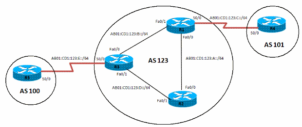
In the example, Router R1, R2 and R3 are part of BGP Autonomous System number 123. R4 is part of Autonomous System 101 and R5 part of Autonomous System 100.
The three routers (R1, R2 and R3) are configured with OSPFv3 for IGP connectivity. IPv6 prefix of loop back interface Lo 0 (1111:111:111:A::/64 eui-64, 2222:222:222:A::/64 eui-64 And 3333:333:333:A::/64 eui-64) of all three routers is advertised in Area 0 of OSPFv3 routing protocol.
IBGP peering is formed between routers R1, R2 and R3 through learnt loopback prefixes. Router R1 and R4 are connected over a WAN link (serial connection) and forms EBGP peering. Similarly router R3 and R5 are forming EBGP peering over WAN link.
Router R4 and R5 inject the same IPv6 prefixes:

1. network BC01:BC1:10:A::/64
2. network BC02:BC1:11:A::/64
3. network BC03:BC1:12:A::/64

As the two Routers R4 and R5 inject the same IPv6 prefixes, the path selection is based on BGP well-known Attributes. In this example, Local Preference is chosen. The BGP Local Preference value of 500 is set for the prefix BC01:BC1:10:A::/64 on router R3 through route-map. This results in R3 as the exit point for this prefix and R1 the exit point for the remaining two prefixes.

Configure

The fast Ethernet interfaces (F0/0 And F0/1) of routers R1, R2 And R3 are IPv6 enabled with IPv6 address of format eui-64.

Network Diagram

This document uses this network setup:
ipv6-bgp-local-preference-config-01.gif

Configurations

This document uses these configurations:

Wednesday, 1 November 2017

VXLAN Configuration

Introduction

This document provides a high level overview of Virtual Extensible LAN (VXLAN) and a few configuration examples followed by verification commands and output.

Requirements

Cisco recommends that you have knowledge of these topics:
  • Multicast routing concepts such as Rendezvous Point (RP) and Platform Independent Multicast (PIM).
  • Virtual Port Channel (vPC) concepts.
This document assumes that the IP routing and multicast routing has been established prior to VXLAN configuration.

Components Used

The information in this document is based on these software and hardware versions:
  • Nexus 9396s as vPC Virtual Tunnel Endpoints (VTEPs) that run Version 7.0(3)I1(1b)
  • Nexus 3172 that runs Version 6.0(2)U5(1)
  • LAN_ENTERPRISE_SERVICES_PKG license installed
The information in this document was created from the devices in a specific lab environment. All of the devices used in this document started with a cleared (default) configuration. If your network is live, make sure that you understand the potential impact of any command.

Background Information

Terminology

VXLAN (Virtual Extensible LAN) - The technology that provides the same Ethernet Layer 2 network services as VLAN does today, but with greater extensibility and flexibility.
VNID (Vxlan Network Identifier) - 24 bit segment ID that defines the broadcast domain. Interchangeable with "VXLAN Segment ID".
VTEP (Virtual Tunnel Endpoint) - This is the device that does the encapsulation and de-encapsulation.
NVE (Network Virtual Interface) - Logical interface where the encapsulation and de-encapsulation occur.

What is VXLAN?

  • VXLAN is a technology which allows overlaying a Layer 2 (L2) network over a Layer 3 (L3) underlay with use of any IP routing protocol.
  • It uses MAC-in-UDP Encapsulation.
VXLAN solves three main problems:
  • 16M VNIs (broadcast domains) versus the 4K offered by traditional VLANs.
  • Allows L2 to be extended anywhere in an IP network.
  • Optimized flooding.

Why VXLAN?

  • VLAN Scalability - VXLAN extends the L2 Segment ID field to 24-bits, which potentially allows up to 16 million unique L2 segments over the same network.
  • L2 Segment Elasticity over L3 Boundary - VXLAN encapsulates an L2 frame in an IP-UDP header, which allows L2 adjacency across router boundaries.
  • Leverages multicast in the transport network in order to simulate flooding behavior for broadcast, unknown unicast, and multicast in the L2 segment.
  • Leverage Equal Cost Multi-pathing (ECMP) in order to achieve optimal path usage over the transport network.

Configure

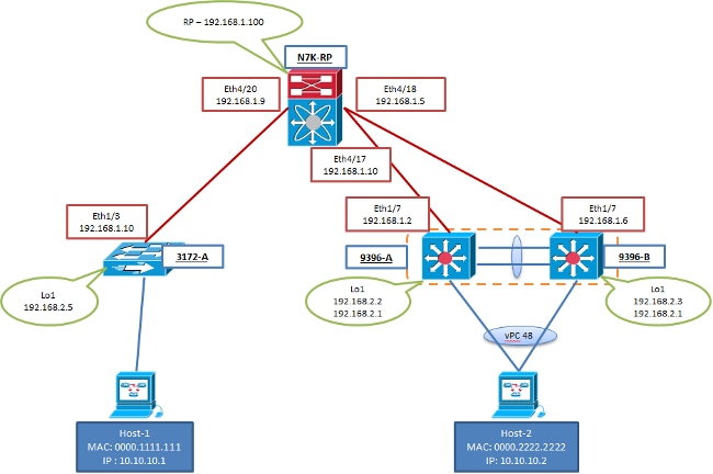
Network Diagram

Configurations

These configurations are specific to the VXLAN portion of configuration. Note that 9396-A and B are in a vPC domain while 3172-A is not. These configurations assume full reachability to all L3 interfaces in the topology with the routing protocol of your choice. Open Shortest Path First (OSPF) was used in this example. It also assumes the multicast routing has been established over these same L3 interfaces.

3172-A


feature ospf
feature pim
feature vn-segment-vlan-based
feature nv overlay

vlan 10
  vn-segment 160010
vlan 20
  vn-segment 160020

interface nve1
  source-interface loopback1
  member vni 160010 mcast-group 231.1.1.1
  member vni 160020 mcast-group 231.1.1.1
  no shutdown
  
interface Ethernet1/3
  no switchport
  ip address 192.168.1.10/30
  ip router ospf 2 area 0.0.0.0
  ip pim sparse-mode

interface loopback1
  ip address 192.168.2.5/32
  ip router ospf 2 area 0.0.0.0
  ip pim sparse-mode
9396-A
feature ospf
feature pim
feature vn-segment-vlan-based
feature nv overlay

ip pim rp-address 192.168.1.100 group-list 224.0.0.0/4

vlan 1,10,20
vlan 10
  vn-segment 160010
vlan 20
  vn-segment 160020

vpc domain 1
  peer-switch
  peer-keepalive destination 10.122.140.99
  peer-gateway

interface port-channel1
  switchport mode trunk
  spanning-tree port type network
  vpc peer-link

interface port-channel48
  switchport mode trunk
  vpc 48  

interface nve1
  mtu 9216
  no shutdown
  source-interface loopback1
  member vni 160010 mcast-group 231.1.1.1
  member vni 160020 mcast-group 231.1.1.1

interface Ethernet1/7
  no switchport
  ip address 192.168.1.2/30
  ip router ospf 1 area 0.0.0.0
  ip pim sparse-mode
  no shutdown
  
interface loopback1
  ip address 192.168.2.2/32
  ip address 192.168.2.1/32 secondary
  ip router ospf 1 area 0.0.0.0
  ip pim sparse-mode

9396-B

feature ospf
feature pim
feature vn-segment-vlan-based
feature nv overlay

ip pim rp-address 192.168.1.100 group-list 224.0.0.0/4

vlan 1,10,20
vlan 10
  vn-segment 160010
vlan 20
  vn-segment 160020
  
vpc domain 1
  peer-switch
  peer-keepalive destination 10.122.140.98
  peer-gateway

interface port-channel1
  switchport mode trunk
  spanning-tree port type network
  vpc peer-link

interface port-channel48
  switchport mode trunk
  vpc 48
 
interface nve1
  mtu 9216
  no shutdown
  source-interface loopback1
  member vni 160010 mcast-group 231.1.1.1
  member vni 160020 mcast-group 231.1.1.1
    
interface Ethernet1/7
  no switchport
  ip address 192.168.1.6/30
  ip router ospf 1 area 0.0.0.0
  ip pim sparse-mode
  no shutdown
  
interface loopback1
  ip address 192.168.2.3/32
  ip address 192.168.2.1/32 secondary
  ip router ospf 1 area 0.0.0.0
  ip pim sparse-mode

MPLS VPN v1

Hi ! everyone on today session we are going to learn about MPLS VPN with the help of packet tracer v7.1 

Introduction

IP version 6 (IPv6) is a new version of IP designed to replace IP version 4 (IPv4), which is currently deployed and used extensively throughout the world. The benefits of IPv6 are primarily a result of its much larger addressing space, which is required to cope with the Internet expansion and with the explosion of Internet-capable appliances.
An IPv6 VPN is connected over an IPv6 interface or sub-interface to the Service Provider (SP) backbone via a PE router. The site can be both IPv4 and IPv6 capable. Each IPv6 VPN has its own address space which means a given address denotes different systems in different VPNs. This is achieved via a new address-family, VPN-IPv6 or VPNv6 address-family, which prep ends a Route Distinguishes (RD) to the IP address.
A VPNv6 address is a 24-byte quantity beginning with an 8-byte RD and ending with a 16-byte IPv6 address. When a site is IPv4 and IPv6 capable, the same RD can be used for the advertisement of both IPv4 and IPv6 addresses.
Note: For IPv6 Virtual Routing and Forwarding (VRF) support on some platforms (for example, the 7600 Series Router), you will need to configure mls ipv6 vrf in global configuration.
Now we are going to look over how to do ipv6 configuration in MPLS VPN with the topology given below as screenshot.
 

Configuration of VRF 


CE1 Router
ipv6 unicast-routing
ipv6 cef
!
interface Serial 0/0
 ipv6 address 2001:1::1/124
!
interface Loopback 0
 ipv6 address ABCD::1/128
!
CE2 Router
ipv6 unicast-routing
ipv6 cef
!
interface Serial 0/0
 ipv6 address 2001:2::1/124
!
interface Loopback 0
 ipv6 address ABCD::2/128
!
6VPE1 Router
ipv6 unicast-routing
ipv6 cef
!
mpls label protocol ldp
mpls ldp router-id Loopback 0 force

! !----- The VRF is defined with vrf definition <vrf-name> and is made IPv6 aware !

vrf definition CUST1
 rd 1:1
 !
 address-family ipv6
 route-target import 1:1
 route-target export 1:1
 exit-address-family
!
interface Serial 0/0
 vrf forwarding CUST1
 ipv6 address 2001:1::2/124
!
interface Loopback 0
 ip address 1.1.1.1 255.255.255.255
 ip ospf 1 area 0

6VPE2 Router
ipv6 unicast-routing
ipv6 cef
!
mpls label protocol ldp
mpls ldp router-id Loopback 0 force
!
vrf definition CUST1
  rd 1:1
 !
 address-family ipv6
 route-target import 1:1
 route-target export 1:1
 exit-address-family
!
interface Serial 0/0
 vrf forwarding CUST1
 ipv6 address 2001:2::2/124
!
interface Loopback 0
 ip address 3.3.3.3 255.255.255.255
 ip ospf 1 area 0
!

Therefore we have completed the lab session on IPv6 MPLS VPN.


Popular Posts