
Young Next Generation for CCNA learners
Wednesday, 29 November 2017
Tuesday, 28 November 2017
Basic BGP Configuration - GNS3 Lab
Hi ! everyone on today we are going to learn about how to configure basic bgp in packet tracer which is shown below in screenshot.

Configuration of both R1 and R2 Routers
R1(config)#interface fastethernet0/0
R1(config-if)#ip address 11.0.0.1 255.255.255.0
R1(config-if)#no shutdown
R1(config-if)#interface loopback 0
R1(config-if)#ip address 1.1.1.1 255.255.255.0
R2(config)#interface fastethernet0/0
R2(config-if)#ip address 11.0.0.2 255.255.255.0
R2(config-if)#no shutdown
R2(config-if)#interface loopback 0
R2(config-if)#ip address 2.2.2.2 255.255.255.0
Next we will configure the BGP configuration part on R1 and R2
R1(config)#router bgp 1
R1(config-router)#neighbor 11.0.0.2 remote-as 2
The configuration is very simple with only two lines on R1. In the first line, BGP configuration begins with a familiar type of command: the router bgp command, where AS number is the BGP AS number used by that router (same as EIGRP, OSPF configuration).
In this case R1 wants to establish BGP neighbor relationship with R2 (in BGP AS 2) so it choose an interface on R2 (Fa0/0: 11.0.0.2) and specify R2 is in BGP AS 2 via the command “neighbor 11.0.0.2 remote-as 2“. At the other end R2 will do the same thing for R1 to set up BGP neighbor relationship.
R2(config)#router bgp 2
R2(config-router)#neighbor 11.0.0.1 remote-as 1
On R2:
%BGP-5-ADJCHANGE: neighbor 11.0.0.1 Up
Next is after forming BGP neighbor relationship we can verify by using the “show ip bgp summary” command on both routers:
On Router R1:

On Router R2:

Let’s try advertising the loopback 0 interface on R1 to R2:
On R1:
R1(config)#router bgp 1
R1(config-router)#network 1.1.1.0 mask 255.255.255.0

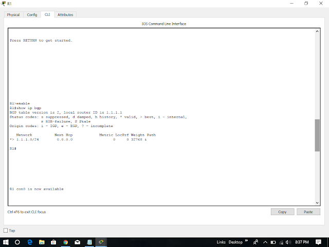
Now the BGP routing tables on these two routers contain this route and the command is show ip bgp


Also in the routing table of R2 we will see this prefix, which is advertised with BGP from R1:

Therefore, we have completed our lab session successfully on configuring bgp using packet tracer version 7.1 and also you can download our pkt file given below.


Configuration of both R1 and R2 Routers
R1(config)#interface fastethernet0/0
R1(config-if)#ip address 11.0.0.1 255.255.255.0
R1(config-if)#no shutdown
R1(config-if)#interface loopback 0
R1(config-if)#ip address 1.1.1.1 255.255.255.0
R2(config)#interface fastethernet0/0
R2(config-if)#ip address 11.0.0.2 255.255.255.0
R2(config-if)#no shutdown
R2(config-if)#interface loopback 0
R2(config-if)#ip address 2.2.2.2 255.255.255.0
Next we will configure the BGP configuration part on R1 and R2
R1(config)#router bgp 1
R1(config-router)#neighbor 11.0.0.2 remote-as 2
The configuration is very simple with only two lines on R1. In the first line, BGP configuration begins with a familiar type of command: the router bgp command, where AS number is the BGP AS number used by that router (same as EIGRP, OSPF configuration).
In this case R1 wants to establish BGP neighbor relationship with R2 (in BGP AS 2) so it choose an interface on R2 (Fa0/0: 11.0.0.2) and specify R2 is in BGP AS 2 via the command “neighbor 11.0.0.2 remote-as 2“. At the other end R2 will do the same thing for R1 to set up BGP neighbor relationship.
R2(config)#router bgp 2
R2(config-router)#neighbor 11.0.0.1 remote-as 1
After a moment we should see a message (on each router) similar to the following, letting us know that an adjacency has been formed:
On R1:
%BGP-5-ADJCHANGE: neighbor 11.0.0.2 UpOn R2:
%BGP-5-ADJCHANGE: neighbor 11.0.0.1 Up
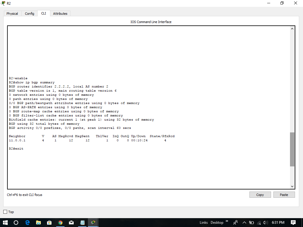
Next is after forming BGP neighbor relationship we can verify by using the “show ip bgp summary” command on both routers:
On Router R1:

On Router R2:
Let’s try advertising the loopback 0 interface on R1 to R2:
On R1:
R1(config)#router bgp 1
R1(config-router)#network 1.1.1.0 mask 255.255.255.0


Now the BGP routing tables on these two routers contain this route and the command is show ip bgp

Note: A blank AS path (only letter “i” is shown) means that the route was originated in the local AS. In the R1 output above, network 1.1.1.0/24 is originated from R1 so we see the path only has one letter “i”.
One notice is on R1 the “Next Hop” is 0.0.0.0 which means this prefix is originated from the local router. On R2 the Next Hop is pointing toward the interface Fa0/0 of R1 (11.0.0.1) to which R2 will send traffic for the destination 1.1.1.0/24.
Now R1 advertised prefix 1.1.1.0/24 to R2 so we can re-check R2 with the “show ip bgp summary” command to see the “Prefix received” increased to 1:


Therefore, we have completed our lab session successfully on configuring bgp using packet tracer version 7.1 and also you can download our pkt file given below.
Configure NAT - GNS3 Lab
Hi ! everyone on today we are going to learn about how to configure nat using packet tracer which is given below.

Staic NAT
R0#configure terminal
R0(config)#int loopback0
R0(config-if)#ip address 10.0.0.1 255.0.0.0
R0(config-if)#ip nat inside
R0(config-if)#int f0/0
R0(config-if)#ip address 200.0.0.1 255.255.255.0
R0(config-if)#no shutdown
R0(config-if)#ip nat outside
R0(config-if)#exit
R0(config)#ip nat inside source static 10.0.0.1 200.0.0.2
R1#config terminal
R1(config)#int f0/0
R1(config-if)#ip address 200.0.0.10 255.255.255.0
R1(config-if)#no shutdown

R0#show ip nat translations

Now if we want to use the extended ping command (without NAT configured) this will be the results shown:

Thus, We can't ping from the loopback interface as shown in above screenshot.
Dynamic NAT
RouterA(config)# access-list 1 permit 192.168.0.0 0.0.0.255
RouterA(config)# ip nat pool PoolforNAT 200.23.123.6 200.23.123.10 netmask 255.255.255.0
RouterA(config)# ip nat inside source list 1 pool PoolforNAT
RouterA(config)# int loopback0
RouterA(config-if)# ip nat inside
RouterA(config-if)# int fa0/0
RouterA(config-if)# ip nat outside
RouterA(config)# access-list 1 permit 192.168.0.0 0.0.0.255
RouterA(config)# ip nat inside source list 1 interface fa0/0 overload
RouterA(config)# interface fa0/0
RouterA(config-if)# ip nat outside
RouterA(config-if)# interface loopback0
RouterA(config-if)# ip nat inside

Staic NAT
R0#configure terminal
R0(config)#int loopback0
R0(config-if)#ip address 10.0.0.1 255.0.0.0
R0(config-if)#ip nat inside
R0(config-if)#int f0/0
R0(config-if)#ip address 200.0.0.1 255.255.255.0
R0(config-if)#no shutdown
R0(config-if)#ip nat outside
R0(config-if)#exit
R0(config)#ip nat inside source static 10.0.0.1 200.0.0.2
R1#config terminal
R1(config)#int f0/0
R1(config-if)#ip address 200.0.0.10 255.255.255.0
R1(config-if)#no shutdown

R0#show ip nat translations

we want to test our NAT configuration we have to ping from R0’s loopback interface by using the ping extended command:
We can use the extended ping command by typing only “ping” at the privileged mode, specify the “target IP address” and type “y” at the “Extended commands” and specify the “source address or interface”
To approve NAT works well we can disable static NAT with the following command
R0(config)#no ip nat inside source static 10.0.0.1 200.0.0.2Now if we want to use the extended ping command (without NAT configured) this will be the results shown:

Thus, We can't ping from the loopback interface as shown in above screenshot.
Dynamic NAT
RouterA(config)# access-list 1 permit 192.168.0.0 0.0.0.255
RouterA(config)# ip nat pool PoolforNAT 200.23.123.6 200.23.123.10 netmask 255.255.255.0
RouterA(config)# ip nat inside source list 1 pool PoolforNAT
RouterA(config)# int loopback0
RouterA(config-if)# ip nat inside
RouterA(config-if)# int fa0/0
RouterA(config-if)# ip nat outside
Configure PAT (NAT Overload)
> Configure a standard access list to define what internal traffic will be translated
> Link the access list to the interface to be used for PAT
> Define interfaces as either inside or outside
PAT router commands> Link the access list to the interface to be used for PAT
> Define interfaces as either inside or outside
RouterA(config)# access-list 1 permit 192.168.0.0 0.0.0.255
RouterA(config)# ip nat inside source list 1 interface fa0/0 overload
RouterA(config)# interface fa0/0
RouterA(config-if)# ip nat outside
RouterA(config-if)# interface loopback0
RouterA(config-if)# ip nat inside
Sunday, 26 November 2017
Configure Static Route - Cisco Packet Tracer
Hi ! everyone on today we are going to look over how to configure static routing GNS3 lab on packet tracer which is shown screenshot given below topology.

This is a simple syntax of static route:
Configuring interfaces on R0
R0(config)#interface s0/0
R0(config-if)#ip address 12.12.12.1 255.255.255.0
R0(config-if)#no shutdown
R0(config-if)#interface loopback0
R0(config-if)#ip address 10.0.0.1 255.0.0.0
R0(config-if)#exit
Configuring interfaces on R1
R0(config)#interface s0/0
R0(config-if)#ip address 12.12.12.2 255.255.255.0
R0(config-if)#no shutdown
R0(config-if)#interface loopback0
R0(config-if)#ip address 172.16.0.1 255.255.0.0
R0(config-if)#exit

Now if we check the routing table of R0 & R1 by the command show ip route on both R0 and R1
Verify
R0#show ip route

R1#show ip route

Configuring static route on R0
R0(config)#ip route 172.16.0.0 255.255.0.0 12.12.12.2
Configuring static route on R1
R1(config)#ip route 10.0.0.0 255.0.0.0 12.12.12.1
Notice that static route works one-way. It means we have to add static route to both R0 and R1 so that R0 and R1 can communicate.


This is a simple syntax of static route:
ip route destination-network-address subnet-mask {next-hop-IP-address | exit-interface}> destination-network-address: destination network address of the remote network
> subnet mask: subnet mask of the destination network
> next-hop-IP-address: the IP address of the receiving interface on the next-hop router
> exit-interface: the local interface of this router where the packets will go out
Now we consider a real-world example of static routing. Suppose that your company has 2 branches located in New York and Chicago. As the administrator of the network, you are tasked to connect them so that employees in the two LANs can communicate with each other. After careful consideration you decided to connect them via static route. > subnet mask: subnet mask of the destination network
> next-hop-IP-address: the IP address of the receiving interface on the next-hop router
> exit-interface: the local interface of this router where the packets will go out
Configuring interfaces on R0
R0(config)#interface s0/0
R0(config-if)#ip address 12.12.12.1 255.255.255.0
R0(config-if)#no shutdown
R0(config-if)#interface loopback0
R0(config-if)#ip address 10.0.0.1 255.0.0.0
R0(config-if)#exit
Configuring interfaces on R1
R0(config)#interface s0/0
R0(config-if)#ip address 12.12.12.2 255.255.255.0
R0(config-if)#no shutdown
R0(config-if)#interface loopback0
R0(config-if)#ip address 172.16.0.1 255.255.0.0
R0(config-if)#exit

Now if we check the routing table of R0 & R1 by the command show ip route on both R0 and R1
Verify
R0#show ip route

R1#show ip route

Configuring static route on R0
R0(config)#ip route 172.16.0.0 255.255.0.0 12.12.12.2
Configuring static route on R1
R1(config)#ip route 10.0.0.0 255.0.0.0 12.12.12.1
Notice that static route works one-way. It means we have to add static route to both R0 and R1 so that R0 and R1 can communicate.
On R0

On R1

Now try to ping each far end network
On R0 ping to check for communication with router R1.

Administrative distance of a static route.
After adding two static routes in R0 & R1 routers, the routing tables of two routers contain these lines:
S 10.0.0.0/8 [1/0] via 12.12.12.1 (on R1)
S 172.16.0.0/16 [1/0] via 12.12.12.2 (on R0)
S 172.16.0.0/16 [1/0] via 12.12.12.2 (on R0)
The “S” letter tells us this is a static route. The networks 10.0.0.0/8 and 172.16.0.0/16 are the destinations of this static route and if the routers want to reach them they must send packets to 12.12.12.1 (on R1) and 12.12.12.2 (on R2). These parameters are straightforward and easy to understand. But what is [1/0]? Well, 1 is the administrative distance (AD) and 0 is the metric of that static route.
The administrative distance is a measure of trustworthiness where lower numbers are considered to be more trustworthy than higher numbers. The route with the lowest administrative distance value is the preferred route that the router selects. Administrative distance is the value from 0 to 255.
Directly connected routes have an administrative distance of 0. Static routes have an administrative distance
of 1 so in the outputs above you will see the administrative distance of both static routes are 1.
of 1 so in the outputs above you will see the administrative distance of both static routes are 1.
The router treats a static route pointing to an interface the same as a connected interface so the its AD is 0. If you configure a static route pointing to an exiting interface (for example: “ip route 172.16.0.0 255.255.0.0 s0/0” on R0) then the AD will not be shown.
Note: For your information, EIGRP has an administrative distance of 90. IGRP has an administrative distance of 100. OSPF has an administrative distance of 110. And RIP has an administrative distance of 120.
Therefore, we have completed our lab session on configure static route in packet tracer version 7.1. For more information you can download our pkt file given below.
Configuring RIP - GNS3 Lab
Hi ! everyone on today we are going to learn about how to configure rip GNS3 lab in packet tracer as before going to the topic we will do A quick summary of RIPv2:

Configuring interfaces for R0, R1 & R2:
On Router R0:
R0(config)#interface s0/0
R0(config-if)#ip address 192.168.1.2 255.255.255.0
R0(config-if)#no shutdown
R0(config-if)#interface loopback0
R0(config)#ip address 12.0.0.1 255.0.0.0
On Router R1:
R1(config)#interface s0/0
R1(config-if)#ip address 192.168.1.1 255.255.255.0
R1(config-if)#no shutdown
R1(config-if)#interface f0/0
R1(config-if)#ip address 192.168.2.1 255.255.255.0
R1(config-if)#no shutdown
On Router R2:
R2(config)#interface f0/0
R2(config-if)#ip address 192.168.2.2 255.255.255.0
R2(config-if)#interface lo0
R2(config-if)#ip address 200.200.200.1 255.255.255.0

Before enable RIP we should check the routing table on these routers to understand what has been changed in these routers.
Verify:
when we check now we look the Serial and FastEthernet are connected properly.
R0#show ip route
R1#show ip route
R2#show ip route


R0#exit
> Routing Information Protocol (RIP) is a true distance-vector routing protocol
> RIP permits a hop count of up to 15, so anything that requires 16 hops is deemed unreachable.
> RIP sends the complete routing table out to all active interfaces every 30 seconds (RIP updates occur every 30 seconds)
> RIP version 2 does send subnet mask information with the route updates. This is called classless routing.
> RIP only uses hop count to determine the best way to a remote network (a hop is a router)
> Administrative Distance is 120
> Support VLSM & dis-contiguous networks we have shown below topology.> RIP permits a hop count of up to 15, so anything that requires 16 hops is deemed unreachable.
> RIP sends the complete routing table out to all active interfaces every 30 seconds (RIP updates occur every 30 seconds)
> RIP version 2 does send subnet mask information with the route updates. This is called classless routing.
> RIP only uses hop count to determine the best way to a remote network (a hop is a router)
> Administrative Distance is 120

Configuring interfaces for R0, R1 & R2:
On Router R0:
R0(config)#interface s0/0
R0(config-if)#ip address 192.168.1.2 255.255.255.0
R0(config-if)#no shutdown
R0(config-if)#interface loopback0
R0(config)#ip address 12.0.0.1 255.0.0.0
On Router R1:
R1(config)#interface s0/0
R1(config-if)#ip address 192.168.1.1 255.255.255.0
R1(config-if)#no shutdown
R1(config-if)#interface f0/0
R1(config-if)#ip address 192.168.2.1 255.255.255.0
R1(config-if)#no shutdown
On Router R2:
R2(config)#interface f0/0
R2(config-if)#ip address 192.168.2.2 255.255.255.0
R2(config-if)#interface lo0
R2(config-if)#ip address 200.200.200.1 255.255.255.0

Before enable RIP we should check the routing table on these routers to understand what has been changed in these routers.
Verify:
when we check now we look the Serial and FastEthernet are connected properly.
R0#show ip route
R1#show ip route
R2#show ip route
Notice that these 3 routers only see the directly connected routers.
Now if you ping from the loopback (or any interface) of R0 to the loopback (or any interface) of R2 then the it will not successful because R0 doesn’t know which interface it should send the packets out to reach network 200.200.200.0.
Now enable RIPv2 on three routers
R0(config)#router rip
R0(config-router)#version 2
R0(config-router)#network 12.0.0.0
R0(config-router)#network 192.168.1.0
R1(config)#router rip
R1(config-router)#version 2
R1(config-router)#network 192.168.1.0
R1(config-router)#network 192.168.2.0
R2(config)#router rip
R2(config-router)#version 2
R2(config-router)#network 200.200.200.0
R2(config-router)#network 192.168.2.0
Notice that with RIP protocol we just need to type the main network without subnet mask or wildcard mask. If you type a subnetwork, it will be auto summary into the main network.
Check the routing tables of these routers we will see the differences
Verify
R0#show ip route

R1#show ip route

R2#show ip route

Now we can ping from the R0’s loopback interface to the R2’s loopback interface as the routing table of R0 has a path to R2’s loopback interface and vice versa.
If you want to check what is inside the update packet, use the command debug ip rip.
R0#debug ip rip
RIP protocol debugging is on
To turn off the debug ip, use the command undebug ip rip. If you want to disable all the debug processes, use the command undebug all.
Therefore, we successfully completed our lab session on configuring rip GNS3 lab is done in packet tracer version 7.1. For more information you can download our Pkt. file given below.
Configure Cisco Router Password - GNS3 Lab
Hi ! everyone on today we are going to learn a simple topic on how to configure cisco router password using packet tracer which is converted from GNS3 as given below topology.

Router>enable
Router#config t
Router(config)#enable password cisco
Router(config)#exit
Router#exit
Now We have logged out the router, notice that you will see two lines “Router con0 is now available” and “Press RETURN to get started.” Press Enter to enter the user mode (a line Router> will appear)

Password: ------> Here you type our password "cisco"
Router#
Notice that we with the “enable password” command, the router will save our password in plain text. It means if someone types show running-config on our router, they can see our password.
Router#show running-config
Building configuration...
Current configuration : 578 bytes
!
version 12.4
no service timestamps log datetime msec
no service timestamps debug datetime msec
no service password-encryption
!
hostname Router
!
!
!
enable password cisco ------->
!
!
!
!
!
!
no ip cef
no ipv6 cef
!
!
!
!
!
!
!
!
!
!
!
!
spanning-tree mode pvst
!
!
!
!
!
!
interface FastEthernet0/0
no ip address
duplex auto
speed auto
shutdown
!
interface FastEthernet0/1
no ip address
duplex auto
speed auto
shutdown
!
interface Vlan1
no ip address
shutdown
!
ip classless
!
ip flow-export version 9
!
!
!
!
!
!
!
line con 0
!
line aux 0
!
line vty 0 4
login
!
!
!
end
This is a thing above we could see the marked symbol like this ---> that we don’t want as our router is not secured completely. In fact, most of the administrators use the “enable secret” command nowadays. To do it, in the privileged mode type the following commands:
Router#config t
Router(config)#enable secret ciscoSecret (notice the letter “S” is capital)
Router(config)#exit
Router#exit
Router>enable
Password: --------> Here type password "cisco" the router does not accept it
Password: --------> Here type password "ciscoSecret" as we mentioned above
Router#

Now we can see the command shows:
enable secret 5 $1$mERr$8HKbj5xhhhd97zc4Svr9p.
enable password cisco
Router(config-line)#password cisco
Router(config-line)#login
Router(config-line)#exit
Router(config)#exit
Set vty (virtual terminal lines) password:
Router#config t
Router(config)#line vty 0 4
Router(config-line)#password cisco
Router(config-line)#login
Router(config-line)#exit
Router(config)#exit
Another notice is that we can’t login to a Cisco router via telnet if we don’t set a vty line password for it.
Therefore, that all for today lab session on configure on cisco router password GNS3 lab done in packet tracer version 7.1.

Router>enable
Router#config t
Router(config)#enable password cisco
Router(config)#exit
Router#exit
Now We have logged out the router, notice that you will see two lines “Router con0 is now available” and “Press RETURN to get started.” Press Enter to enter the user mode (a line Router> will appear)

Now we can test if the password is working. Log in the privileged mode with the enable command
Router>enable
Now we can see the router is asking for a password. Type “cisco” as its password here and we can log in to the privileged mode
Router>enablePassword: ------> Here you type our password "cisco"
Router#
Notice that we with the “enable password” command, the router will save our password in plain text. It means if someone types show running-config on our router, they can see our password.
Router#show running-config
Building configuration...
Current configuration : 578 bytes
!
version 12.4
no service timestamps log datetime msec
no service timestamps debug datetime msec
no service password-encryption
!
hostname Router
!
!
!
enable password cisco ------->
!
!
!
!
!
!
no ip cef
no ipv6 cef
!
!
!
!
!
!
!
!
!
!
!
!
spanning-tree mode pvst
!
!
!
!
!
!
interface FastEthernet0/0
no ip address
duplex auto
speed auto
shutdown
!
interface FastEthernet0/1
no ip address
duplex auto
speed auto
shutdown
!
interface Vlan1
no ip address
shutdown
!
ip classless
!
ip flow-export version 9
!
!
!
!
!
!
!
line con 0
!
line aux 0
!
line vty 0 4
login
!
!
!
end
This is a thing above we could see the marked symbol like this ---> that we don’t want as our router is not secured completely. In fact, most of the administrators use the “enable secret” command nowadays. To do it, in the privileged mode type the following commands:
Router#config t
Router(config)#enable secret ciscoSecret (notice the letter “S” is capital)
Router(config)#exit
Router#exit
Router>enable
Password: --------> Here type password "cisco" the router does not accept it
Password: --------> Here type password "ciscoSecret" as we mentioned above
Router#
So notice that if you configure the enable secret command, it takes precedence over the enable password command. The two commands cannot be in effect simultaneously.
The enable secret command will encrypt the password so no one can see the password with the show running-config command. We can check it.

Now we can see the command shows:
enable secret 5 $1$mERr$8HKbj5xhhhd97zc4Svr9p.
enable password cisco
We can also set the password for console and vty (telnet) login with these commands:
Set console password:
Router(config)#line console 0Router(config-line)#password cisco
Router(config-line)#login
Router(config-line)#exit
Router(config)#exit
Set vty (virtual terminal lines) password:
Router#config t
Router(config)#line vty 0 4
Router(config-line)#password cisco
Router(config-line)#login
Router(config-line)#exit
By default, a Cisco router supports 5 simultaneous telnet sessions. By using the command line vty 0 4, the configuration below will be applied to all 5 sessions (line 0 to line 4).
Notice these passwords are not encrypted and we can see them with the “show running-config” command. We can encrypt all the passwords with the service password-encryption command in global configuration mode
Router(config)#service password-encryptionRouter(config)#exit
Another notice is that we can’t login to a Cisco router via telnet if we don’t set a vty line password for it.
Therefore, that all for today lab session on configure on cisco router password GNS3 lab done in packet tracer version 7.1.
EIGRP GNS3 Lab
Hi ! everyone on today we are going to learn eigrp GNS3 lab which is done in packet tracer v 7.1 given below screenshot is the topology.


Step 1 – Configuring IP addresses on the routers
On R1:
R1#config t
R1(config)#int s0/0
R1(config-if)#ip address 192.168.30.12 255.255.255.240
R1(config-if)#no shut
R1(config-if)#int s0/1
R1(config-if)#ip address 192.168.30.18 255.255.255.240
R1(config-if)#no shut
R1(config-if)#int s0/2
R1(config-if)#ip address 192.168.30.35 255.255.255.240
R1(config-if)#no shut
R1(config-if)#int f0/0
R1(config-if)#ip address 192.168.60.10 255.255.255.240
R1(config-if)#no shut
On R2:
R2#config t
R2(config)#int s0/0
R2(config-if)#ip address 192.168.30.13 255.255.255.240
R2(config-if)#no shut
R2#config t
R2(config)#int s0/0
R2(config-if)#ip address 192.168.30.13 255.255.255.240
R2(config-if)#no shut
On R3:
R3#config t
R3(config)#int f0/0
R3(config-if)#ip address 192.168.60.13 255.255.255.240
R3(config-if)#no shut
R3#config t
R3(config)#int f0/0
R3(config-if)#ip address 192.168.60.13 255.255.255.240
R3(config-if)#no shut
On R4:
R4#config t
R4(config)#int s0/0
R4(config-if)#ip address 192.168.30.20 255.255.255.240
R4(config-if)#no shut
R4#config t
R4(config)#int s0/0
R4(config-if)#ip address 192.168.30.20 255.255.255.240
R4(config-if)#no shut
On R5:
R5#config t
R5(config)#int s0/0
R5(config-if)#ip address 192.168.30.40 255.255.255.240
R5(config-if)#no shut
R5#config t
R5(config)#int s0/0
R5(config-if)#ip address 192.168.30.40 255.255.255.240
R5(config-if)#no shut
Now all the interfaces are up. We should check the interfaces on R1 to confirm this with the “show ip int brief” command
Notice that all both the “Status” and “Protocol” of the connected interfaces were up.
Also, We can see all the neighbors of R1 with the “show cdp neighbors” command on R1 given below.

At this time we can ping between two directly connected interfaces. For example a ping from s0/0 of R1 to s0/0 of R2 (192.168.30.13) will be successful.
But a ping between two far-away interfaces is not successful. For example a ping from R2 to s0/0 of R4 (192.168.30.20) will be unsuccessful.
Step 2 – Enable EIGRP on all the routers
On R1
R1(config)#router eigrp 100
R1(config-router)#network 192.168.30.0
R1(config-router)#network 192.168.60.0
R1(config-router)#no auto-summary
R1(config)#router eigrp 100
R1(config-router)#network 192.168.30.0
R1(config-router)#network 192.168.60.0
R1(config-router)#no auto-summary
On R2
R2(config)#router eigrp 100
R2(config-router)#network 192.168.30.0
R2(config-router)#no auto-summary
R2(config)#router eigrp 100
R2(config-router)#network 192.168.30.0
R2(config-router)#no auto-summary
On R3
R3(config)#router eigrp 100
R3(config-router)#network 192.168.60.0
R3(config-router)#no auto-summary
R3(config)#router eigrp 100
R3(config-router)#network 192.168.60.0
R3(config-router)#no auto-summary
On R4
R4(config)#router eigrp 100
R4(config-router)#network 192.168.30.0
R4(config-router)#no auto-summary
R4(config)#router eigrp 100
R4(config-router)#network 192.168.30.0
R4(config-router)#no auto-summary
On R5
R5(config)#router eigrp 100
R5(config-router)#network 192.168.30.0
R5(config-router)#no auto-summary
R5(config)#router eigrp 100
R5(config-router)#network 192.168.30.0
R5(config-router)#no auto-summary
After typing above commands we will see the neighbors adjacency on these routers are up.
Now the EIGRP process is up and we can ping from anywhere. For example a ping from R2 to s0/0 of R4 (192.168.30.20) will be successful now.

By checking the routing table of R2, R3, R4 & R5 we can confirm EIGRP has been implemented successfully. For example, using the “show ip route” command on R5 we see below screenshot.

We can check the neighbor relationships on these routers with the “show ip eigrp neighbors” command. Below is an example of R1:

To see the topologies of these routers, use the “show ip eigrp topology” command. Below is the output of R4.

Therefore, we have successfully completed our lab session on eigrp lab on packet tracer version 7.1. For more detailed information for simulation you can have our file from download button the given below.
Saturday, 25 November 2017
TAMBI Report 1
TAMBI Report 1
S.NO
|
Topics
from my Packet tracer for youngccnaguru
|
Download
Files
|
1
|
DHCP SIM
|
|
2
|
CCNA VTP SIM
|
|
3
|
CCNA RIP Configuration Question
|
|
4
|
CCNA RIP Configuration Q & A
|
|
5
|
CCNA NAT SIM Q & A
|
|
6
|
CCNA Implementation Questions
|
|
7
|
CCNA Implementation Q & A
|
|
8
|
CCNA EIGRP Troubleshooting SIM Q & A
|
|
9
|
CCNA EIGRP Lab SIM Q & A
|
|
10
|
CCNA EIGRP Lab SIM Question
|
|
11
|
CCNA Drag and Drop SIM Q & A
|
|
12
|
CCNA Access List SIM Q & A
|
|
13
|
CCNA Access List SIM 2
|
Subscribe to:
Posts (Atom)
Popular Posts
-
 IPv6 Static NAT Configuration Hi ! everyone on today we are going to learn about IPv6 static NAT configuration. Which will be shown as ...
 -
 Hi ! everyone on today we are going to learn a simple topic on how to configure cisco router password using packet tracer which is converte...
 -
 Hi ! everyone on today we are going to learn about how to configure basic bgp in packet tracer which is shown below in screenshot. Con...