
Hi ! everyone on today we are going to learn about how to configure basic bgp in packet tracer which is shown below in screenshot.

Configuration of both R1 and R2 Routers
R1(config)#interface fastethernet0/0
R1(config-if)#ip address 11.0.0.1 255.255.255.0
R1(config-if)#no shutdown
R1(config-if)#interface loopback 0
R1(config-if)#ip address 1.1.1.1 255.255.255.0
R2(config)#interface fastethernet0/0
R2(config-if)#ip address 11.0.0.2 255.255.255.0
R2(config-if)#no shutdown
R2(config-if)#interface loopback 0
R2(config-if)#ip address 2.2.2.2 255.255.255.0
Next we will configure the BGP configuration part on R1 and R2
R1(config)#router bgp 1
R1(config-router)#neighbor 11.0.0.2 remote-as 2
The configuration is very simple with only two lines on R1. In the first line, BGP configuration begins with a familiar type of command: the router bgp command, where AS number is the BGP AS number used by that router (same as EIGRP, OSPF configuration).
In this case R1 wants to establish BGP neighbor relationship with R2 (in BGP AS 2) so it choose an interface on R2 (Fa0/0: 11.0.0.2) and specify R2 is in BGP AS 2 via the command “neighbor 11.0.0.2 remote-as 2“. At the other end R2 will do the same thing for R1 to set up BGP neighbor relationship.
R2(config)#router bgp 2
R2(config-router)#neighbor 11.0.0.1 remote-as 1
On R2:
%BGP-5-ADJCHANGE: neighbor 11.0.0.1 Up
Next is after forming BGP neighbor relationship we can verify by using the “show ip bgp summary” command on both routers:
On Router R1:

On Router R2:

Let’s try advertising the loopback 0 interface on R1 to R2:
On R1:
R1(config)#router bgp 1
R1(config-router)#network 1.1.1.0 mask 255.255.255.0

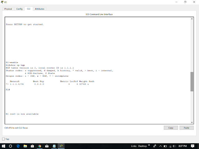
Now the BGP routing tables on these two routers contain this route and the command is show ip bgp


Also in the routing table of R2 we will see this prefix, which is advertised with BGP from R1:

Therefore, we have completed our lab session successfully on configuring bgp using packet tracer version 7.1 and also you can download our pkt file given below.


Configuration of both R1 and R2 Routers
R1(config)#interface fastethernet0/0
R1(config-if)#ip address 11.0.0.1 255.255.255.0
R1(config-if)#no shutdown
R1(config-if)#interface loopback 0
R1(config-if)#ip address 1.1.1.1 255.255.255.0
R2(config)#interface fastethernet0/0
R2(config-if)#ip address 11.0.0.2 255.255.255.0
R2(config-if)#no shutdown
R2(config-if)#interface loopback 0
R2(config-if)#ip address 2.2.2.2 255.255.255.0
Next we will configure the BGP configuration part on R1 and R2
R1(config)#router bgp 1
R1(config-router)#neighbor 11.0.0.2 remote-as 2
The configuration is very simple with only two lines on R1. In the first line, BGP configuration begins with a familiar type of command: the router bgp command, where AS number is the BGP AS number used by that router (same as EIGRP, OSPF configuration).
In this case R1 wants to establish BGP neighbor relationship with R2 (in BGP AS 2) so it choose an interface on R2 (Fa0/0: 11.0.0.2) and specify R2 is in BGP AS 2 via the command “neighbor 11.0.0.2 remote-as 2“. At the other end R2 will do the same thing for R1 to set up BGP neighbor relationship.
R2(config)#router bgp 2
R2(config-router)#neighbor 11.0.0.1 remote-as 1
After a moment we should see a message (on each router) similar to the following, letting us know that an adjacency has been formed:
On R1:
%BGP-5-ADJCHANGE: neighbor 11.0.0.2 UpOn R2:
%BGP-5-ADJCHANGE: neighbor 11.0.0.1 Up
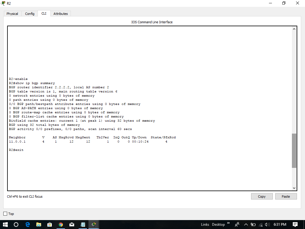
Next is after forming BGP neighbor relationship we can verify by using the “show ip bgp summary” command on both routers:
On Router R1:

On Router R2:
Let’s try advertising the loopback 0 interface on R1 to R2:
On R1:
R1(config)#router bgp 1
R1(config-router)#network 1.1.1.0 mask 255.255.255.0


Now the BGP routing tables on these two routers contain this route and the command is show ip bgp

Note: A blank AS path (only letter “i” is shown) means that the route was originated in the local AS. In the R1 output above, network 1.1.1.0/24 is originated from R1 so we see the path only has one letter “i”.
One notice is on R1 the “Next Hop” is 0.0.0.0 which means this prefix is originated from the local router. On R2 the Next Hop is pointing toward the interface Fa0/0 of R1 (11.0.0.1) to which R2 will send traffic for the destination 1.1.1.0/24.
Now R1 advertised prefix 1.1.1.0/24 to R2 so we can re-check R2 with the “show ip bgp summary” command to see the “Prefix received” increased to 1:


Therefore, we have completed our lab session successfully on configuring bgp using packet tracer version 7.1 and also you can download our pkt file given below.


No comments:
Post a Comment