Introduction
This document describes how the Open Shortest Path First (OSPF) protocol between Nexus and Cisco IOS® feature is implemented in Cisco IOS and Nexus Operating System (NXOS).
Prerequisites
Requirements
Cisco recommends that you have knowledge of the OSPF protocol.
Components Used
The information in this document is based on these software and hardware versions:
- NXOS Version 6.2(6a)
- Cisco IOS Version 15.1(4)M1
Background Information
Cisco IOS devices support RFC 1583. However NXOS supports RFC 2328 and there are designs wherein this difference can create routing loops in the network when there are external OSPF routes in the network.
Important Information
The difference between RFC 1583 and RFC 2328, in regard to how to choose the best route among multiple external routes, is discussed in this section.
Abstract from RFC 1583 Section 16.4.6
In order to compare Type 1 external paths, look at the sum of the distance to the forwarding address and the advertised Type 1 metric (X+Y). In order to compare Type 2 external paths, look at the advertised Type 2 metrics, and then if necessary the distance to the forwarding addresses.
If the new path is shorter, it replaces the present paths in the routing table entry. If the new path is the same cost, it is added to the routing table entry's list of paths.
If the new path is shorter, it replaces the present paths in the routing table entry. If the new path is the same cost, it is added to the routing table entry's list of paths.
Abstract from RFC 2328 Section 16.4.1
Intra-area paths that use non-backbone areas are always the most preferred. The other paths, intra-area backbone paths and inter-area paths, are of equal preference.
Configure
Scenario 1
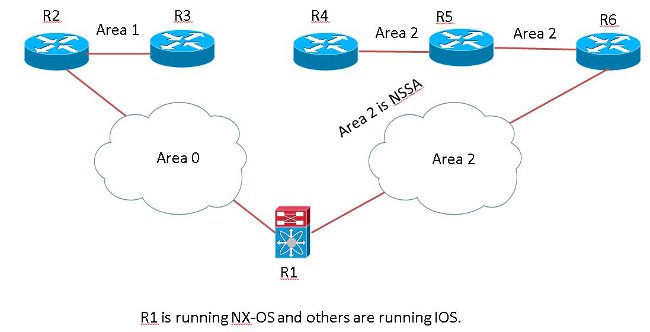
Network Diagram
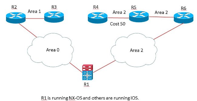
R3 and R4 redistribute the same network 172.16.1.0/24 with the same metric as the OSPF external type E2 route. R6 prefers the route advertised by R3 because the forward metric to the ASBR R3 is lower than to R4 and the next-hop for 172.16.1.0/24 is R1. (As per RFC 1583, the path selection is based solely on cost.)
R6#sh ip ospf border-routers

OSPF Router with ID (192.168.6.6) (Process ID 1)

Base Topology (MTID 0)

Internal Router Routing Table
Codes: i - Intra-area route, I - Inter-area route

i 192.168.4.4 [51] via 192.168.56.5, GigabitEthernet0/0, ASBR, Area 2, SPF 17
 >>>> Cost is 51 to reach R4 ASBR.
i 192.168.1.1 [1] via 192.168.16.1, GigabitEthernet0/1, ABR, Area 2, SPF 17
I 192.168.3.3 [42] via 192.168.16.1, GigabitEthernet0/1, ASBR, Area 2, SPF 17
 >>>> Cost is 42 to reach R3 ASBR

R6#sh ip route 172.16.1.0
Routing entry for 172.16.1.0/24
Known via "ospf 1", distance 110, metric 20, type extern 2, forward metric 42
Last update from 192.168.16.1 on GigabitEthernet0/1, 00:02:13 ago
Routing Descriptor Blocks:
* 192.168.16.1, from 192.168.3.3, 00:02:13 ago, via GigabitEthernet0/1
Route metric is 20, traffic share count is 1
R1 prefers the route advertised by R4 despite the higher cost because it is an intra-area route to ASBR. The route does not go through the backbone area and the next-hop is R6 ( as per RFC 2328).
R1-NXOS# sh ip ospf border-routers
OSPF Process ID 1 VRF default, Internal Routing Table
Codes: i - Intra-area route, I - Inter-area route

intra 192.168.2.2 [40], ABR, Area 0.0.0.0, SPF 18
via 192.168.12.2, Eth4/43
inter 192.168.3.3 [41], ASBR, Area 0.0.0.0, SPF 18 >>>> Cost is 41
via 192.168.12.2, Eth4/43
intra 192.168.4.4 [91], ASBR, Area 0.0.0.2, SPF 18 >>>> Cost is 91
via 192.168.16.6, Eth4/44

switch-R1-NXOS# sh ip route 172.16.1.0
IP Route Table for VRF "default"
'*' denotes best ucast next-hop
'**' denotes best mcast next-hop
'[x/y]' denotes [preference/metric]
'%' in via output denotes VRF

172.16.1.0/24, ubest/mbest: 1/0
*via 192.168.16.6, Eth4/44, [110/20], 00:10:41, ospf-1, type-2
This causes a loop in the network as R6 sends the packets to R1 and R1 sends them back to R6.
R5#traceroute 172.16.1.1 numeric
 Type escape sequence to abort.
Tracing the route to 172.16.1.1
VRF info: (vrf in name/id, vrf out name/id)
1 192.168.56.6 4 msec 0 msec 0 msec
2 192.168.16.1 4 msec 0 msec 4 msec
3 192.168.16.6 0 msec 4 msec 0 msec
4 192.168.16.1 4 msec 0 msec 4 msec
5 192.168.16.6 0 msec 4 msec 0 msec
As you see, the packet loops between R1 and R6. In order to resolve this issue, you need to change the RFC compatibility on the NXOS.
R1-NXOS(config)# router ospf 1
R1-NXOS(config-router)# rfc1583compatibility

switch-R1-NXOS# sh ip route 172.16.1.0
IP Route Table for VRF "default"
'*' denotes best ucast next-hop
'**' denotes best mcast next-hop
'[x/y]' denotes [preference/metric]
'%' in via output denotes VRF

172.16.1.0/24, ubest/mbest: 1/0
*via 192.168.12.2, Eth4/43, [110/20], 00:00:40, ospf-1, type-2
Now, R1 correctly points it to R2 and the loop is removed from the network.
R5#traceroute 172.16.1.1 numeric
Type escape sequence to abort.
Tracing the route to 172.16.1.1
VRF info: (vrf in name/id, vrf out name/id)
1 192.168.56.6 0 msec 4 msec 0 msec
2 192.168.16.1 0 msec 0 msec 0 msec
3 192.168.12.2 4 msec 0 msec 0 msec
4 192.168.23.3 4 msec 0 msec 4 msec
5 192.168.23.3 4 msec 0 msec 4 msec
Scenario 2
Network Diagram
R1 receives an NSSA-External (Type 7) route from R6 and an External (Type 5) route from R2 for the same prefix 172.16.1.0/24. R1 prefers Type 7, though normally in OSPF Type 5 is preferred over Type 7.
R1-NXOS# sh ip ospf database nssa-external 172.16.1.0 detail
OSPF Router with ID (192.168.1.1) (Process ID 1 VRF default)

Type-7 AS External Link States (Area 0.0.0.2)

   LS age: 914
   Options: 0x28 (No TOS-capability, Type 7/5 translation, DC)
   LS Type: Type-7 AS-External
   Link State ID: 172.16.1.0 (Network address)
   Advertising Router: 192.168.4.4                 >>>>> Type 7 originated by R4
 and installed in the RIB.
   LS Seq Number: 0x80000001
   Checksum: 0x3696
   Length: 36
   Network Mask: /24
         Metric Type: 2 (Larger than any link state path)
         TOS: 0
         Metric: 20
         Forward Address: 192.168.45.4
         External Route Tag: 0>


R1-NXOS# sh ip ospf database external 172.16.1.0 detail
 OSPF Router with ID (192.168.1.1) (Process ID 1 VRF default)


Type-5 AS External Link States

    LS age: 853
   Options: 0x2 (No TOS-capability, No DC)
   LS Type: Type-5 AS-External
   Link State ID: 172.16.1.0 (Network address)
   Advertising Router: 192.168.1.1         >>>>> Since Type 7 is installed
 in the RIB, it was converted to type 5
   LS Seq Number: 0x80000001
   Checksum: 0xb545
   Length: 36
   Network Mask: /24
         Metric Type: 2 (Larger than any link state path)
         TOS: 0<
         Metric: 20
         Forward Address: 192.168.45.4
         External Route Tag: 0<

   LS age: 596
   Options: 0x20 (No TOS-capability, DC)
   LS Type: Type-5 AS-External
   Link State ID: 172.16.1.0 (Network address)
   Advertising Router: 192.168.3.3              >>>>>>  Type 5 is also received from R3
   LS Seq Number: 0x80000002
   Checksum: 0x2250
   Length: 36
   Network Mask: /24
         Metric Type: 2 (Larger than any link state path)>
         TOS: 0
         Metric: 20<>
         Forward Address: 0.0.0.0
         External Route Tag: 0


R1-NXOS# sh ip route 172.16.1.0
IP Route Table for VRF "default"
'*' denotes best ucast next-hop
'**' denotes best mcast next-hop
'[x/y]' denotes [preference/metric]
'%<string>' in via output denotes VRF <string>

172.16.1.0/24, ubest/mbest: 1/0
    *via 192.168.16.6, Eth4/44, [110/20], 00:16:54, ospf-1, nssa type-2     >>>> Type 7
 route is installed in RIB.
Since R1 does not have the rfc1583compatibility command configured under the OSPF router process and the route's Type 5 Link State Advertisement's (LSA's) adv-router-id is reachable in area 0 (backbone router), OSPF always picks up the path for the route via the non-backbone area. In this case the next-hop is chosen in area 2 (as per RFC 2328).
R1-NXOS(config)# router ospf 1
R1-NXOS(config-router)# rfc1583compatibility

R1-NXOS# sh ip route 172.16.1.0
IP Route Table for VRF "default"
'*' denotes best ucast next-hop
'**' denotes best mcast next-hop
'[x/y]' denotes [preference/metric]
'%<string>' in via output denotes VRF <string>

172.16.1.0/24, ubest/mbest: 1/0
    *via 192.168.12.2, Eth4/43, [110/20], 00:00:04, ospf-1, type-2     >>>> Type 5
 route is installed in RIB.
Recommendation
There are other design or network scenarios wherein this compatibility issue can cause loops or suboptimal routing in the network if the network has NXOS and Cisco IOS that run together with OSPFv2.
Cisco recommends to use the RFC 1583 compatibility command in the NXOS OSPF router configuration mode if the network includes devices which only support RFC1583, that is Cisco IOS.
Verify
There is currently no verification procedure available for this configuration.
Troubleshoot
There is currently no specific troubleshooting information available for this configuration.