Recent Posts

Showing posts with label CCNA Lab. Show all posts

Friday, 23 August 2019

ACL (Access Control Lists)

Hi everyone, on today we are going to learn about ACL (i.e, Access Control Lists) in simplified terms and how ACL works with an example.

In simple points, ACL  ;
  • There are filters that enable you to control which routing updates or packets are permitted or denied in or out of a network.
  • They are specifically used by network administrators to filter traffic and to provide extra security for the network (i.e., This can be applied to Cisco routers).
  • ACLs provide a powerful way to control traffic into and out of your network 
  • This control can be as simple as permitting or denying network hosts or addresses.
How it works ? explained below in simplified format with example ;
A router acts as a packet filter when it forwards or denies packets according to filtering rules. As a Layer 3 device, a packet-filtering router uses rules to determine whether to permit or deny traffic based on source and destination IP addresses, source port and destination port, and the protocol of the packet.

To simplify this note, how ACL or a router uses packet filtering works with a example given below.

Example: Imagine a guard stationed at a locked door. The guard’s instruction is to allow only people whose names appear on a guest list to pass through the door. The guard is filtering people based on the condition of having their names on the authorized list.

When a packet arrives at the router, the router extracts certain information from the packet header and makes decisions according to the filter rules as to whether the packet can pass through or be dropped.

Packet filtering process works at the Network layer of the Open Systems Interconnection (OSI) model or the Internet layer of TCP/IP.

Watch this video given below by click this PLAY > button to see about extended ACL configuration how of our CCNA Lab. Also make sure to share and subscribe our channel. 

Wednesday, 7 August 2019

How to connect switch with two devices ?

Hi, everyone on today we are going to learn switch connection between two devices like, "PC and Laptop". Also we will see how packets communicate each other.

As we all know that switch is an intelligent device with multiple ports and know we will see how switch connecting PC and Laptop in cisco packet tracer.

In 3 simplified steps :-

Step 1: Open cisco packet tracer go to network and devices now select Switch there will be many but i had selected 2960-24TT devices for practice.  
Step 2: Now we have to select end devices i.e., PC and Laptop. Try to connect both PC and Laptop with copper straight-through cable connecting to switch ports.


Step 3: Finally, we could see that green light in triangle symbol which means it is connected. But first we have to enter ip address for both PC and Laptop then only we could see switch intelligent device communication between PC and Laptop.


Stay tuned for next information to learn and share this to your friends also subscribe to our YouTube channel. 

Tuesday, 12 December 2017

LACP configure verifying and troubleshooting

LACP Configuration in verifying and troubleshooting

Hi !!! everyone on today we are going to learn about how configure verifying and troubleshooting in LACP. 

What do you know about LACP ?

Link Aggregation Control Protocol (LACP) is a protocol for the collective handling of multiple physical ports that can be seen as a single channel for network traffic purposes. This serves the general principle of link aggregation, which describes the effort of setting up parallel network structures to provide redundancy, or to improve performance.

This is LACP configure by preparing topology which is given below as screenshots .


Step 1: First we have to configure LACP in Switch@


Step 2: Now we can configure LACP in Switch!


Step 3: Verifying both Switches in LACP configuration


Switch@:


After configuring in Switch@ we have to move on to switch! for checking summary.


Finally, we have completed our lab session that how to configure LACP by verifying and troubleshooting in the cisco Packet tracer version 7.0. 

Friday, 24 November 2017

IPv6 OSPF Configuration SIM

Hi ! everyone on today we are going to look over The basic features of the OSPFv3 routing protocol are almost same as provided by OSPFv2. However, OSPFv3 is designed to support IPv6-capable networks. In the previous posts, we have discussed a lot about the OSPF routing protocol.


Step by step configuration on ospf for ipv6

To configure OSPF for IPv6, we will use the following topology. You can use either Cisco Packet Tracer or GNS3 depending on your choice to create the following topology.


Once you have created the preceding topology, configure the following IPv6 addresses on the routers.

IPv6 Address Table for OSPFv3

Once you have configured the preceding IPv6 addresses, you can start to configure OSPFv3 routing. In order to configure the OSPFv3 routing, first, we would like to discuss the high-level steps used to configure OSPFv3 routing:
  1. Enabling IPv6 routing: In order to enable IPv6 routing on a router, you need to use ipv6 unicast-routing
  2. Assigning an OSPF router ID: In order to assign an OSPF router ID, you need to use the router-id <router-id> command in the router configuration mode.
  3. Defining areas and enabling OSPFv3 on the desired interfaces: In order to define an area and enable the OSPFv3 routing on an interface, you need to use the ipv6 ospf <process ID> area <area number> command in the interface configuration mode.

Configure OSPF for ipv6 on Router1

Once you have understood the high-level steps to configure OSPFv3, let’s begin the step by step OSPFv3 configuration.

1. On Router1, execute the ipv6 unicast-routing command at the global configuration mode to enable IPv6 routing.
Router1(config)#ipv6 unicast-routing
2. Next, configure 1.1.1.1/8 ipv4 address on the loopback0 interface. This IP address will be used as router-id for this router.
Router1(config)#int loopback1
Router1(config-if)#ip address 1.1.1.1 255.0.0.0
Router1(config-if)#exit

3. Next step is to create an OSPFv3 process and define the router ID.

Router1(config)#ipv6 router ospf 1
Router1(config-rtr)#router-id 1.1.1.1

Router1(config-rtr)#exit

4. Next is to enable OSPFv3 routing on the interfaces that you want to advertise in the network, in this example, we will enable OSPFv3 routing on the FastEthernet0/0 interface.

Router1(config)#int fa0/0
Router1(config-if)#ipv6 address 2001:abcd:0123:1::1/64

Router1(config-if)#ipv6 ospf 1 area 0
Router1(config-if)#no shutdown
Router1(config)#exit


Configure OSPF for ipv6 on Router2

Once you have configured OSPFv3 on Router1, move on to Router2 and execute the following commands.
1. Execute the ipv6 unicast-routing command at the global configuration mode to enable the IPv6 Routing.
Router2(config)#ipv6 unicast-routing
2. Next, configure 2.2.2.2/8 IPv4 address on the lo0 loopback interface. This IP address will be used as router-id for this router.
Router2(config-if)#ip add 2.2.2.2 255.0.0.0
Router2(config-if)#exit


3.Next, create an OSPFv3 process and define the router ID.
Router2(config)#ipv6 router ospf 1
Router2(config-rtr)#router-id 2.2.2.2
Router2(config-rtr)#exit

4. Next enable OSPFv3 routing on the interfaces that you want to advertise in the network.

Router2(config)#int fa0/0
Router2(config-if)#ipv6 ospf 1 area 0
OSPFv3: No IPV6 enabled on this interface
Router2(config-if)#ipv6 add 2001:abcd:0123:1::2/64
Router2(config-if)#no shut
Router2(config-if)#exit

Router2(config)#int fa0/1
Router2(config-if)#ipv6 add 2002:abcd:0123:2::1/64
Router2(config-if)#ipv6 ospf 1 area 1
Router2(config-if)#no shut
Router2(config-if)#exit


Configure OSPF for ipv6 on Router3


Once you have configured OSPFv3 on Router1 and Router2, move on to Router3 and execute the following commands.
Router3(config)#ipv6 unicast-routing
Router3(config)#int loopback1
Router3(config-if)#ip add 3.3.3.3 255.0.0.0
Router3(config-if)#exit
Router3(config)#ipv6 router ospf 1
Router3(config-rtr)#router-id 3.3.3.3
Router3(config-rtr)#exit

Router3(config)#int fa0/1
Router3(config-if)#ipv6 add 2002:abcd:0123:2::2/64
Router3(config-if)#ipv6 ospf 1 area 1
Router3(config-if)#no shut
Router3(config-if)#exit

Verify the configurations

Well, you have successfully configured OSPFv3 on all the routers. Now, it’s time to verify your configuration using through these commands as follows:

1. show ipv6 route
2. show ipv6 ospf neighbor
3. show ipv6 ospf interface
4. show ipv6 ospf border-routers


Saturday, 4 November 2017

IPv6 ACL on Telnet

Hi ! Everyone on today we are going to learn about how to configure ipv6 ACL on telnet.

Step 1: Configure ipv6 address on Router
Router>enable

Router#config t

Enter configuration commands, one per line. End with CNTL/Z.

Router(config)#ipv6 unicast-routing

Router(config)#int fa0/0

Router(config-if)#ipv6 add 2000::1/64

Router(config-if)#no shut

Router(config-if)#exit

Router(config)#int fa0/1

Router(config-if)#ipv6 add 2001::1/64

Router(config-if)#no shut
STEP 2: Configure Telnet on Cisco Router.

Router>enable

Router#config t

Enter configuration commands, one per line. End with CNTL/Z.

Router(config)#enable password redhat

Router(config-line)#line vty 0 4

Router(config-line)#password ccna123

Router(config-line)#login

Router(config-line)#

STEP 3:Configure IPv6 ACL on TELNET


Router(config)#line vty 0 4

Router(config-line)#ipv6 access-list CCNP

Router(config-ipv6-acl)#deny ipv6 host 2000::2 any

Router(config-ipv6-acl)#permit ipv6 any any

Router(config-ipv6-acl)#exit

STEP 4: Now Apply the ACL rule created above for TELNET


Router(config)#line vty 0 4

Router(config-line)#ipv6 access-class CCNP in

Router(config-line)#exit

Router(config)#

STEP 5:Now troubleshoot and test your ACL rule.

Test telnet connection by trying to telnet your router machine from different hosts.
Check and find whether the hosts you blocked from telnet are blocked or not.
Also check other hosts which are not blocked from telnet are able to telnet your router.


STEP 6: SEE the ACL rules created.


Router#show ipv6 access-list

IPv6 access list CCNP

deny ipv6 host 2000::2 any (4 match(es))

permit ipv6 any any (1 match(es))
Therefore, we have successfully completed our ipv6 lab session on ACL telnet.

Wednesday, 1 November 2017

MPLS VPN v1

Hi ! everyone on today session we are going to learn about MPLS VPN with the help of packet tracer v7.1 

Introduction

IP version 6 (IPv6) is a new version of IP designed to replace IP version 4 (IPv4), which is currently deployed and used extensively throughout the world. The benefits of IPv6 are primarily a result of its much larger addressing space, which is required to cope with the Internet expansion and with the explosion of Internet-capable appliances.
An IPv6 VPN is connected over an IPv6 interface or sub-interface to the Service Provider (SP) backbone via a PE router. The site can be both IPv4 and IPv6 capable. Each IPv6 VPN has its own address space which means a given address denotes different systems in different VPNs. This is achieved via a new address-family, VPN-IPv6 or VPNv6 address-family, which prep ends a Route Distinguishes (RD) to the IP address.
A VPNv6 address is a 24-byte quantity beginning with an 8-byte RD and ending with a 16-byte IPv6 address. When a site is IPv4 and IPv6 capable, the same RD can be used for the advertisement of both IPv4 and IPv6 addresses.
Note: For IPv6 Virtual Routing and Forwarding (VRF) support on some platforms (for example, the 7600 Series Router), you will need to configure mls ipv6 vrf in global configuration.
Now we are going to look over how to do ipv6 configuration in MPLS VPN with the topology given below as screenshot.
 

Configuration of VRF 


CE1 Router
ipv6 unicast-routing
ipv6 cef
!
interface Serial 0/0
 ipv6 address 2001:1::1/124
!
interface Loopback 0
 ipv6 address ABCD::1/128
!
CE2 Router
ipv6 unicast-routing
ipv6 cef
!
interface Serial 0/0
 ipv6 address 2001:2::1/124
!
interface Loopback 0
 ipv6 address ABCD::2/128
!
6VPE1 Router
ipv6 unicast-routing
ipv6 cef
!
mpls label protocol ldp
mpls ldp router-id Loopback 0 force

! !----- The VRF is defined with vrf definition <vrf-name> and is made IPv6 aware !

vrf definition CUST1
 rd 1:1
 !
 address-family ipv6
 route-target import 1:1
 route-target export 1:1
 exit-address-family
!
interface Serial 0/0
 vrf forwarding CUST1
 ipv6 address 2001:1::2/124
!
interface Loopback 0
 ip address 1.1.1.1 255.255.255.255
 ip ospf 1 area 0

6VPE2 Router
ipv6 unicast-routing
ipv6 cef
!
mpls label protocol ldp
mpls ldp router-id Loopback 0 force
!
vrf definition CUST1
  rd 1:1
 !
 address-family ipv6
 route-target import 1:1
 route-target export 1:1
 exit-address-family
!
interface Serial 0/0
 vrf forwarding CUST1
 ipv6 address 2001:2::2/124
!
interface Loopback 0
 ip address 3.3.3.3 255.255.255.255
 ip ospf 1 area 0
!

Therefore we have completed the lab session on IPv6 MPLS VPN.


Friday, 29 September 2017

Configuring an IPv6 Network with RIPng

Configuring an IPv6 Network with RIPng

Hi ! everyone on today we are going to learn about how to configure an ipv6 network with RIPng with simplified explanation given below as screenshots with our topology.


Step 1: First we should assign ipv6 address to all PCs

PC0


 PC1

PC2

Step 2: We have to configure ipv6 with RIPng on Router R1
Router>enable
Router#configure terminal
Enter configuration commands, one per line. End with CNTL/Z.
Router(config)#hostname R1
R1(config)#ipv6 unicast-routing
R1(config)#interface g0/0
R1(config-if)#ipv6 address FE80::1 link-local
R1(config-if)#ipv6 address 2001:DB8:DA:1::1/64
R1(config-if)#ipv6 rip RIP1 enable
R1(config-if)#no shutdown


Now we can see the green color is the changed state to up on Router R1 connected to Switch1.

R1(config-if)#interface s0/0/0
R1(config-if)#ipv6 address FE80::1 link-local
R1(config-if)#ipv6 address 2001:DB8:DA:2::1/64
R1(config-if)#ipv6 rip RIP1 enable
R1(config-if)#ipv6 rip RIP1 default-information originate
R1(config-if)#clock rate 128000

R1(config-if)#no shutdown
%LINK-5-CHANGED: Interface Serial0/0/0, changed state to down
R1(config-if)#interface s0/0/1
R1(config-if)#ipv6 address FE80::1 link-local
R1(config-if)#ipv6 address 2001:DB8:DA:C::2/64
R1(config-if)#no shutdown

%LINK-5-CHANGED: Interface Serial0/0/1, changed state to down
R1(config-if)#exit
R1(config)#ipv6 route ::/0 s0/0/1

R1(config)#exit

R1#copy running-config startup-config
Destination filename [startup-config]?
Building configuration...

[OK]

We can check our Router R1 by running-configure

R1#show running-config
Building configuration...

Current configuration : 1079 bytes
!
version 15.1
no service timestamps log datetime msec
no service timestamps debug datetime msec
no service password-encryption
!
hostname R1
!
!
!
!
!
!
!
!
no ip cef
ipv6 unicast-routing
!
no ipv6 cef
!
!
!
!
license udi pid CISCO1941/K9 sn FTX1524U2PY
!
!
!
!
!
!
!
!
!
!
!
spanning-tree mode pvst
!
!
!
!
!
!
interface GigabitEthernet0/0
no ip address
duplex auto
speed auto
ipv6 address FE80::1 link-local
ipv6 address 2001:DB8:DA:1::1/64
ipv6 rip RIP1 enable
!
interface GigabitEthernet0/1
no ip address
duplex auto
speed auto
shutdown
!
interface Serial0/0/0
no ip address
ipv6 address FE80::1 link-local
ipv6 address 2001:DB8:DA:2::1/64
ipv6 rip RIP1 enable
ipv6 rip RIP1 default-information originate
clock rate 128000
!
interface Serial0/0/1
no ip address
ipv6 address FE80::1 link-local
ipv6 address 2001:DB8:DA:C::2/64
clock rate 2000000
!
interface Vlan1
no ip address
shutdown
!
ipv6 router rip RIP1
!
ip classless
!
ip flow-export version 9
!
ipv6 route ::/0 Serial0/0/1
!
!
!
!
!
!
line con 0
!
line aux 0
!
line vty 0 4
login
!
!
!

end


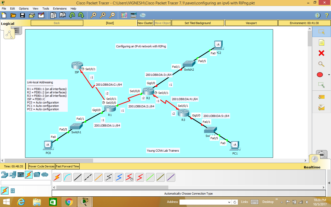
Step 3: After completing on router R1 we have to configure ipv6 on Router R2 with RIPng 

Router>enable
Router#configure terminal
Enter configuration commands, one per line. End with CNTL/Z.
Router(config)#hostname R2
R2(config)#ipv6 unicast-routing
R2(config)#interface s0/0/0
R2(config-if)#ipv6 address FE80::2 link-local
R2(config-if)#ipv6 address 2001:DB8:DA:2::2/64

R2(config-if)#no shutdown


We can see the Router R2 connected with R1 turns to green color which means it changed state to up.

R2(config-if)#interface g0/0
R2(config-if)#ipv6 address FE80::2 link-local
R2(config-if)#ipv6 address 2001:DB8:DA:3::1/64

R2(config-if)#no shutdown


On the above screenshot we can see R2 connects Switch2 it shows in green color is that changed state to up.

R2(config-if)#interface s0/0/1
R2(config-if)#clock rate 128000
R2(config-if)#ipv6 address FE80::2 link-local
R2(config-if)#ipv6 address 2001:DB8:DA:4::1/64

R2(config-if)#no shutdown


R2(config-if)#ipv6 rip RIP1 enable
R2(config-if)#interface s0/0/0
R2(config-if)#ipv6 rip RIP1 enable
R2(config-if)#interface g0/0
R2(config-if)#ipv6 rip RIP1 enable

R2(config-if)#

R2#show run
Building configuration...

Current configuration : 976 bytes
!
version 15.1
no service timestamps log datetime msec
no service timestamps debug datetime msec
no service password-encryption
!
hostname R2
!
!
!
!
!
!
!
!
no ip cef
ipv6 unicast-routing
!
no ipv6 cef
!
!
!
!
license udi pid CISCO1941/K9 sn FTX15242L3O
!
!
!
!
!
!
!
!
!
!
!
spanning-tree mode pvst
!
!
!
!
!
!
interface GigabitEthernet0/0
no ip address
duplex auto
speed auto
ipv6 address 2001:DB8:DA:3::1/64
ipv6 rip RIP1 enable
!
interface GigabitEthernet0/1
no ip address
duplex auto
speed auto
shutdown
!
interface Serial0/0/0
no ip address
ipv6 address FE80::2 link-local
ipv6 address 2001:DB8:DA:2::2/64
ipv6 rip RIP1 enable
!
interface Serial0/0/1
no ip address
ipv6 address FE80::2 link-local
ipv6 address 2001:DB8:DA:4::1/64
ipv6 rip RIP1 enable
clock rate 128000
!
interface Vlan1
no ip address
shutdown
!
ipv6 router rip RIP1
!
ip classless
!
ip flow-export version 9
!
!
!
!
!
!
!
line con 0
!
line aux 0
!
line vty 0 4
login
!
!
!
end


R2#show ipv6 route
IPv6 Routing Table - 7 entries
Codes: C - Connected, L - Local, S - Static, R - RIP, B - BGP
U - Per-user Static route, M - MIPv6
I1 - ISIS L1, I2 - ISIS L2, IA - ISIS interarea, IS - ISIS summary
O - OSPF intra, OI - OSPF inter, OE1 - OSPF ext 1, OE2 - OSPF ext 2
ON1 - OSPF NSSA ext 1, ON2 - OSPF NSSA ext 2
D - EIGRP, EX - EIGRP external
R ::/0 [120/2]
via FE80::1, Serial0/0/0
R 2001:DB8:DA:1::/64 [120/2]
via FE80::1, Serial0/0/0
C 2001:DB8:DA:2::/64 [0/0]
via Serial0/0/0, directly connected
L 2001:DB8:DA:2::2/128 [0/0]
via Serial0/0/0, receive
C 2001:DB8:DA:3::/64 [0/0]
via GigabitEthernet0/0, directly connected
L 2001:DB8:DA:3::1/128 [0/0]
via GigabitEthernet0/0, receive
L FF00::/8 [0/0]
via Null0, receive

R2#exit


On R1 router we can check by show ipv6 route command. 
R1>enable
R1#show ipv6 route
IPv6 Routing Table - 6 entries
Codes: C - Connected, L - Local, S - Static, R - RIP, B - BGP
U - Per-user Static route, M - MIPv6
I1 - ISIS L1, I2 - ISIS L2, IA - ISIS interarea, IS - ISIS summary
O - OSPF intra, OI - OSPF inter, OE1 - OSPF ext 1, OE2 - OSPF ext 2
ON1 - OSPF NSSA ext 1, ON2 - OSPF NSSA ext 2
D - EIGRP, EX - EIGRP external
C 2001:DB8:DA:1::/64 [0/0]
via GigabitEthernet0/0, directly connected
L 2001:DB8:DA:1::1/128 [0/0]
via GigabitEthernet0/0, receive
C 2001:DB8:DA:2::/64 [0/0]
via Serial0/0/0, directly connected
L 2001:DB8:DA:2::1/128 [0/0]
via Serial0/0/0, receive
R 2001:DB8:DA:3::/64 [120/2]
via FE80::2, Serial0/0/0
L FF00::/8 [0/0]
via Null0, receive

R1#

Step 4: Configure Router R3 on ipv6 with RIPng

Router>enable
Router#configure terminal
Enter configuration commands, one per line. End with CNTL/Z.
Router(config)#hostname R3
R3(config)#ipv6 unicast-routing
R3(config)#interface s0/0/1
R3(config-if)#ipv6 address FE80::3 link-local
R3(config-if)#ipv6 address 2001:DB8:DA:4::2/64

R3(config-if)#no shutdown


Now in this step we can see green color which is change in state to up by connecting R2 router.

R3(config-if)#ipv6 rip RIP1 enable
R3(config-if)#interface g0/0
R3(config-if)#ipv6 address FE80::3 link-local
R3(config-if)#ipv6 address 2001:DB8:DA:5::1/64

R3(config-if)#no shutdown


We can see the change in state to up with show green color by connecting Switch3.

R3#copy run start
Destination filename [startup-config]?
Building configuration...

[OK]

On router R2 we have to do copy run start command as shown below.
R2>enable
R2#copy run start
Destination filename [startup-config]?
Building configuration...

[OK]

Step 5: Finally we have to configure on ipv6 ISP router with RIPng

Router>enable
Router#configure terminal
Enter configuration commands, one per line. End with CNTL/Z.
Router(config)#hostname ISP
ISP(config)#ipv6 unicast-routing

ISP(config)#interface s0/0/1
ISP(config-if)#clock rate 128000
ISP(config-if)#ipv6 address FE80::C link-local
ISP(config-if)#ipv6 address 2001:DB8:DA:C::1/64

ISP(config-if)#no shutdown


ISP(config-if)#exit
ISP(config)#ipv6 route 2001:DB8:DA::/61 s0/0/1

ISP(config)#exit

ISP#copy run start
Destination filename [startup-config]?
Building configuration...

[OK]

Now we can check by pinging on PC0 with ISP router as shown below


Therefore, all the routers and switches are connected each other with all PCs that the change in state to up. In this session we have learned how to configure ipv6 with RIPng with the help of packet tracer version 7.1.

Popular Posts