Introduction
This document describe how to configure and verify Virtual Extensible LAN (VXLAN) flood and learn mode over IPv4 Multicast transport. VXLAN is designed to provide the same Ethernet Layer 2 network services as VLAN. VXLAN encapsulates MAC address over UDP packet which makes a Layer 2 packet carried over a Layer 3 network. So, it is basically a MAC-in-UDP header.
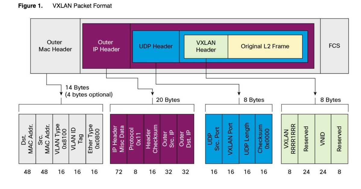
VXLAN introduces an 8 byte VXLAN header that consists of a 24 bit VNID and a few reserved bits. The VXLAN header together with the original Ethernet frame goes in the UDP payload. The 24 bit VNID is used to identify Layer 2 segments and to maintain Layer 2 isolation between th e segments. With all 24 bits in VNID, VXLAN can support 16 million LAN segments. So it resolves the issue of limitation of VLAN. Without VxLAN we can have only 4094 no of vlan, with increased demand modern networks need more vlans , and VXLAN is solution to address the issue .
Since it uses the ethernet frame to encapsulate the packet, so ethernet properties need to remain intact like broadcase , unknown unicast and multicast. To address these type of traffic multicast is being used. In this document VxLAN flood and learn is being described. As the name specify that it will flood the packet and will learn the remote end. It means that data-plane is not up all the times, as soon as traffic will flow data-plane will be built up and will expire as soon as mac address expires.
Prerequisites
Cisco recommends that you have knowledge of basic IP multicast.
Packet Format of VXLAN
As shown in above figure original frame is being encasulated in VxLAN header which is of 8 byte and VNID is of 24 bit. That is further encapsulated in UDP header and outer header would be an IP header.
Source IP address is IP of encapsulating VTEP (Virtual Terminal End Point) and destination IP either would be a multicast or unicast one. VXLAN uses VXLAN tunnel endpoint (VTEP) devices to map tenants's end devices to VXLAN segments and to perform VXLAN encapsulation and de-encapsulation. Each VTEP has two interfaces: One is a switch interface on the local LAN segment to support local endpoint communication through bridging, and the other is an IP interface to the transport IP network.
Remote VTEP Discovery
When the host will start sending the traffic below process will happen. At this moment VTEP does not know the mac address of the remote host .
- End station will send ARP packet for remote end station.
- Packet will reach to VTEP-A and since VTEP-A does not know about the VTEP-B , it will encapsulate the packet inside VxLAN header. It will put the multicast IP address as the destination IP address. Since the same multicast address will be used by all VTEPs, all will join that same multicast group.
- This packet will reach to all VTEP and will be decapsulated, in this way remote VTEP will learn about the other VTEP. Since the decapsulated VTEP will be having the VNID, it will be forwarded in the vlan having the same VNID configured.
- Now remote end will send the ARP reply packet and it will reach to VTEP-B, since now VTEP-B knows about VTEP-A it will again encapsulated the orginal frame but now the destination IP address will be of VTEP-B and it will be unicast IP address .
- ARP reply will reach to VTEP-A and now VTEP-A gets to know about VTEP-B it will form the neighbor relationship with VTEP-B .
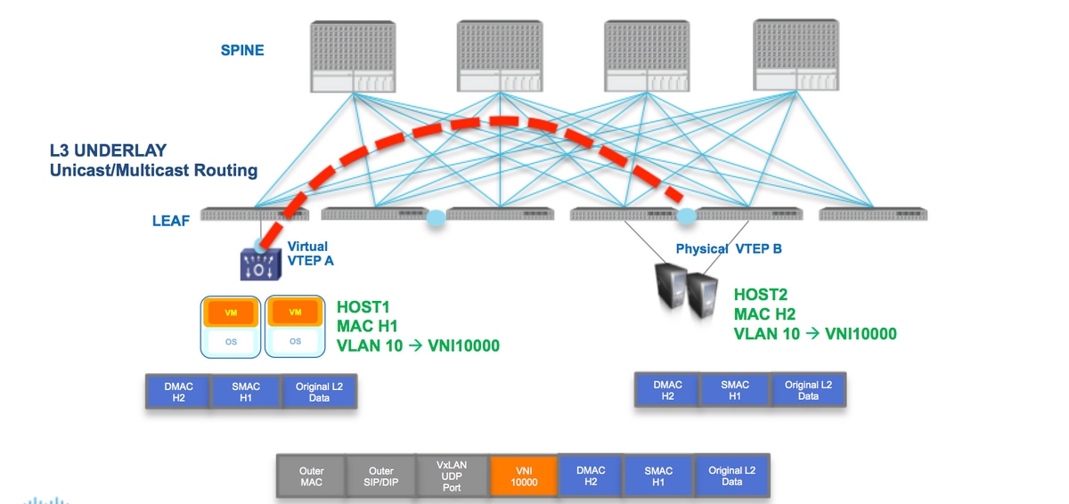
As shown in the diagram Host H1 belongs to vlan 10 and being encapsulted in VNID 10000. As shown above SMAC with H1 and DMAC with H2 is being encapsulated inside VNI 1000 and Source IP and Destination IP could be multicast or unicast described in above section .
Components Used
This document is specific to Nexus platform.
The information in this document was created from the devices in a specific lab environment. All of the devices used in this document started with a cleared (default) configuration. If your network is live, make sure that you understand the potential impact of any command.
Configure
Network Diagram
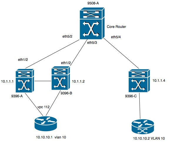
- 9396-A and 9396-B are the VPC peers considerd as VTEP-1.
- 9396-C is the VTEP-2.
- Above diagram is having two host in vlan 10 i.e. 10.10.10.1 and 10.10.10.2.
- VLAN 10 is being used with VNID as 10010.
- 230.1.1.1 is being used as multicast group.
Configurations
To enable VXLAN on Nexus we need to enable the below feature
9396-A config
!
feature vn-segment-vlan-based
feature nv overlay
!
vlan 10
  vn-segment 10010   ------> 10010 is VNID
!
interface nve1
  no shutdown
  source-interface loopback0
  member vni 10010 mcast-group 230.1.1.1
!
interface eth1/2
!
ip pim sparse-mode
!
interface loopback0
  ip address 10.1.1.1/32
  ip address 10.1.1.10/32 secondary
  ip router ospf 9k area 0.0.0.0
  ip pim sparse-mode
!
!
feature vpc
!
vpc domain 1
  peer-switch
  peer-keepalive destination 10.31.113.41 source 10.31.113.40
  peer-gateway
!
interface port-channel1
  vpc peer-link
!
interface port-channel112
  vpc 112
!

9396-B Config
!
vlan 10
  vn-segment 10010   ------>    10010 is VNID
!
interface nve1
  no shutdown
  source-interface loopback0
  member vni 10010 mcast-group 230.1.1.1
!
interface eth1/2
ip pim sparse-mode
!
interface loopback0
  ip address 10.1.1.2/32
  ip address 10.1.1.10/32 secondary
  ip router ospf 9k area 0.0.0.0
  ip pim sparse-mode
!
feature vpc
!
vpc domain 1
  peer-switch
  peer-keepalive destination 10.31.113.40 source 10.31.113.41
  peer-gateway
!
interface port-channel1
  vpc peer-link
!
interface port-channel112
  vpc 112
!

9508-A Config
feature pim

ip pim rp-address 10.1.1.5 group-list 224.0.0.0/4
ip pim ssm range 232.0.0.0/8


interface loopback0
  ip pim sparse-mode

interface Ethernet5/2
  ip pim sparse-mode

interface Ethernet5/3
  ip pim sparse-mode

interface Ethernet5/4
  ip pim sparse-mode

9396-C Config
!
vlan 10
  vn-segment 10010
!
interface loopback0
  ip address 10.1.1.3/32
  ip router ospf 9k area 0.0.0.0
  ip pim sparse-mode
!
interface nve1
  no shutdown
  source-interface loopback0
  member vni 10010 mcast-group 230.1.1.1
!
int eth1/2
ip pim sparse-mode
!

Verify

As of now host has not started sending the packet stream. Since 9396-A is a VPC holding device it will originates the traffic sourcing from the secondary IP address and will act as source IP address for multicast stream.
9396-A# sh nve interface
Interface: nve1, State: Up, encapsulation: VXLAN
 VPC Capability: VPC-VIP-Only [notified]
 Local Router MAC: d8b1.9076.9053
 Host Learning Mode: Data-Plane
 Source-Interface: loopback0 (primary: 10.1.1.1, secondary: 10.1.1.10)

9396-A# sh ip mroute 230.1.1.1IP Multicast Routing Table for VRF "default"

(*, 230.1.1.1/32), uptime: 01:09:34, ip pim nve
  Incoming interface: Ethernet1/2, RPF nbr: 192.168.10.2
  Outgoing interface list: (count: 1)
    nve1, uptime: 00:11:20, nve


(10.1.1.3/32, 230.1.1.1/32), uptime: 00:12:19, ip mrib pim nve
  Incoming interface: Ethernet1/2, RPF nbr: 192.168.10.2
  Outgoing interface list: (count: 1)
    nve1, uptime: 00:11:20, nve

(10.1.1.10/32, 230.1.1.1/32), uptime: 00:11:20, nve ip mrib pim
  Incoming interface: loopback0, RPF nbr: 10.1.1.10
  Outgoing interface list: (count: 1)
    Ethernet1/2, uptime: 00:11:20, pim


In *,G entry nve interface is popultaed in OIL (Outgoing Interface List).  As shown above 10.1.1.10 is source of multiacast stream and nve interface will be the Last hop router for the multicast stream with eth1/2 facing towards core is outgoing interface.

As there is no traffic flowing from host so there are no nve peers:
9396-A# show  mac address-table vlan 10Legend:
        * - primary entry, G - Gateway MAC, (R) - Routed MAC, O - Overlay MAC
        age - seconds since last seen,+ - primary entry using vPC Peer-Link,
        (T) - True, (F) - False
   VLAN     MAC Address      Type      age     Secure NTFY Ports
---------+-----------------+--------+---------+------+----+------------------
*   10     8c60.4f93.5ffc   dynamic  0         F      F    Po112   >> This mac is for host 10.10.10.1


9396-A# sh nve peers
Interface Peer-IP          State LearnType Uptime   Router-Mac
--------- ---------------  ----- --------- -------- -----------------

Following output shows how vPC output should look like:
9396-A# sh vpc brief
Legend:
                (*) - local vPC is down, forwarding via vPC peer-link

vPC domain id                     : 1
Peer status                       : peer adjacency formed ok
vPC keep-alive status             : peer is alive
Configuration consistency status  : success
Per-vlan consistency status       : success
Type-2 consistency status         : success
vPC role                          : primary
Number of vPCs configured         : 1
Peer Gateway                      : Enabled
Dual-active excluded VLANs        : -
Graceful Consistency Check        : Enabled
Auto-recovery status              : Disabled
Delay-restore status              : Timer is off.(timeout = 30s)
Delay-restore SVI status          : Timer is off.(timeout = 10s)

vPC Peer-link status
---------------------------------------------------------------------
id   Port   Status Active vlans
--   ----   ------ --------------------------------------------------
1    Po1    up     1-10

vPC status
----------------------------------------------------------------------
id   Port   Status Consistency Reason                     Active vlans
--   ----   ------ ----------- ------                     ------------
112  Po112  up     success     success                    1-10

9396-A# sh vpc consistency-parameters global

    Legend:
        Type 1 : vPC will be suspended in case of mismatch

Name                        Type  Local Value            Peer Value
-------------               ----  ---------------------- -----------------------Vlan to Vn-segment Map      1     1 Relevant Map(s)      1 Relevant Map(s)
STP Mode                    1     Rapid-PVST             Rapid-PVST
STP Disabled                1     None                   None
STP MST Region Name         1     ""                     ""
STP MST Region Revision     1     0                      0
STP MST Region Instance to  1
 VLAN Mapping
STP Loopguard               1     Disabled               Disabled
STP Bridge Assurance        1     Enabled                Enabled
STP Port Type, Edge         1     Normal, Disabled,      Normal, Disabled,
BPDUFilter, Edge BPDUGuard        Disabled               Disabled
STP MST Simulate PVST       1     Enabled                Enabled
Nve Admin State, Src Admin  1     Up, Up, 10.1.1.10, DP  Up, Up, 10.1.1.10, DP
 State, Secondary IP, Host
 Reach Mode
Nve Vni Configuration       1     10010                  10010
Nve encap Configuration     1     vxlan                  vxlan
Interface-vlan admin up     2
Interface-vlan routing      2     1                      1
capability
Allowed VLANs               -     1-10                   1-10
Local suspended VLANs       -     -                      -

9508-A :

Since 9508-A route is core router, it will not be aware about the VXLAN , it will be aware about the mroute entry only as shown below:
9508-A# sh ip mroute 230.1.1.1
IP Multicast Routing Table for VRF "default"

(*, 230.1.1.1/32), uptime: 01:30:06, pim ip
  Incoming interface: loopback0, RPF nbr: 10.1.1.5, uptime: 01:30:06
  Outgoing interface list: (count: 3)
    Ethernet5/3, uptime: 00:14:11, pim
    Ethernet5/2, uptime: 00:14:31, pim
    Ethernet5/4, uptime: 00:16:22, pim

(10.1.1.3/32, 230.1.1.1/32), uptime: 00:15:44, pim mrib ip
  Incoming interface: Ethernet5/4, RPF nbr: 192.168.10.10, uptime: 00:15:44, internal
  Outgoing interface list: (count: 2)
    Ethernet5/3, uptime: 00:14:11, pim
    Ethernet5/2, uptime: 00:14:31, pim

(10.1.1.10/32, 230.1.1.1/32), uptime: 00:14:31, pim mrib ip
  Incoming interface: Ethernet5/2, RPF nbr: 192.168.10.1, uptime: 00:14:31, internal
  Outgoing interface list: (count: 1)
    Ethernet5/4, uptime: 00:14:31, pim

9396-C
9396-C# show ip mroute
IP Multicast Routing Table for VRF "default"

(*, 230.1.1.1/32), uptime: 01:07:34, ip pim nve
  Incoming interface: Ethernet1/2, RPF nbr: 192.168.10.9
  Outgoing interface list: (count: 1)
    nve1, uptime: 00:10:38, nve


(10.1.1.3/32, 230.1.1.1/32), uptime: 00:10:38, nve ip mrib pim
  Incoming interface: loopback0, RPF nbr: 10.1.1.3
  Outgoing interface list: (count: 1)
    Ethernet1/2, uptime: 00:09:49, pim

(10.1.1.10/32, 230.1.1.1/32), uptime: 00:08:05, ip mrib pim nve
  Incoming interface: Ethernet1/2, RPF nbr: 192.168.10.9
  Outgoing interface list: (count: 1)
    nve1, uptime: 00:08:05, nve

Status after traffic flow startes between peers

As soon as host 1 i.e. 10.10.10.1 starts sending the traffic to 10.10.10.2 NVE peer comes up:
9396-A# sh mac address-table dynamic
Legend:
        * - primary entry, G - Gateway MAC, (R) - Routed MAC, O - Overlay MAC
        age - seconds since last seen,+ - primary entry using vPC Peer-Link,
        (T) - True, (F) - False
   VLAN     MAC Address      Type      age     Secure NTFY Ports
---------+-----------------+--------+---------+------+----+------------------
*   10     8c60.4f93.5ffc   dynamic  0         F      F    Po112
+   10     8c60.4f93.647c   dynamic  0         F      F    nve1(10.1.1.3)


9396-A# sh nve peers
Interface Peer-IP          State LearnType Uptime   Router-Mac
--------- ---------------  ----- --------- -------- -----------------
nve1      10.1.1.3         Up    DP        00:00:14 n/a


9396-A# sh nve peers detail
Details of nve Peers:
----------------------------------------
Peer-Ip: 10.1.1.3
    NVE Interface       : nve1
    Peer State          : Up
    Peer Uptime         : 00:04:49
    Router-Mac          : n/a
    Peer First VNI      : 10010
    Time since Create   : 00:04:49
    Configured VNIs     : 10010
    Provision State     : add-complete
    Route-Update        : Yes
    Peer Flags          : None
    Learnt CP VNIs      : --
    Peer-ifindex-resp   : Yes
----------------------------------------

9396-A sh nve vni 10010 detail
VNI: 10010
  NVE-Interface       : nve1
  Mcast-Addr          : 230.1.1.1
  VNI State           : Up
  Mode                : data-plane
  VNI Type            : L2 [10]
  VNI Flags           :
  Provision State     : add-complete
  Vlan-BD             : 10
  SVI State           : n/a

9396-A# sh nve internal vni 10010
VNI 10010
  Ready-State         : Ready [L2-vni-flood-learn-ready]

Similarly on 9396-C  NVE peers should be up:
9396-C# show mac address-table dynamic
Legend:
        * - primary entry, G - Gateway MAC, (R) - Routed MAC, O - Overlay MAC
        age - seconds since last seen,+ - primary entry using vPC Peer-Link,
        (T) - True, (F) - False
   VLAN     MAC Address      Type      age     Secure NTFY Ports
---------+-----------------+--------+---------+------+----+------------------
*   10     8c60.4f93.5ffc   dynamic  0         F      F    nve1(10.1.1.10)
*   10     8c60.4f93.647c   dynamic  0         F      F    Eth1/13

9396-C# sh nve peers
Interface Peer-IP          State LearnType Uptime   Router-Mac
--------- ---------------  ----- --------- -------- -----------------
nve1      10.1.1.10        Up    DP        00:08:28 n/a

9396-C# sh nve peers detail
Details of nve Peers:
----------------------------------------
Peer-Ip: 10.1.1.10
    NVE Interface       : nve1
    Peer State          : Up
    Peer Uptime         : 00:08:32
    Router-Mac          : n/a
    Peer First VNI      : 10010
    Time since Create   : 00:08:32
    Configured VNIs     : 10010
    Provision State     : add-complete
    Route-Update        : Yes
    Peer Flags          : None
    Learnt CP VNIs      : --
    Peer-ifindex-resp   : Yes
----------------------------------------

9396-C sh nve vni 10010 detail
VNI: 10010
  NVE-Interface       : nve1
  Mcast-Addr          : 230.1.1.1
  VNI State           : Up
  Mode                : data-plane
  VNI Type            : L2 [10]
  VNI Flags           :
  Provision State     : add-complete
  Vlan-BD             : 10
  SVI State           : n/a

9396-C# sh nve internal vni 10010
VNI 10010
  Ready-State         : Ready [L2-vni-flood-learn-ready]


As shown in above, nve peers are based upon data-plane learning and it uses flood and learn mechanism. In case mac address gets timed out nve peer will go down.